Pressure regulators of the RDUK-2 type, developed by Mosgaz-project at the suggestion of engineer. F. F. Kazantsev, are intended to reduce gas pressure in gas pipelines from high to high, medium and low pressure, as well as from medium to medium and low.
Regulators can be used in looped and dead-end urban networks, regulatory stations, industrial and municipal gasified facilities.
These regulators are direct-acting regulators with a command device.
The supra-diaphragm space of the impulse tube control regulator is connected to the gas pipeline downstream of the pressure regulator. Thus, the pressure above the control regulator membrane is always equal to the gas pressure in the gas pipeline. Pressure regulators of the RDUK-2 type are designed for nominal diameters of 50, 100 and 200 mm. The pressure under the control regulator membrane is equal to atmospheric pressure. When the pressure in the gas pipeline is equal to the set one, the force from the gas pressure on the control regulator membrane is equal to the spring force. In this case, the control regulator valve is partially open.
When the pressure in the gas pipeline decreases, the spring overcomes the force from the gas pressure on the membrane, as a result of which the latter rises upward, increasing the opening of the valve. As the pressure increases, the valve opening decreases. Consumption; of gas flowing through the control regulator valve is proportional to its opening value. To set the control regulator to the required pressure, the spring compression is changed.
The control tube control head is connected to the sub-diaphragm space of the control valve, which is connected by a tube to the sub-valve space. For the control valve to operate, the pressure in the submembrane space must create a force greater than the sum of the forces created by the inlet pressure on the valve and the outlet pressure on the membrane in the supra-membrane space.
The necessary pressure difference between the sub-membrane and above-membrane spaces is created due to the presence of chokes in the tubes.
Control regulators KN2 and KV2 are used as a command device.
Pressure regulators of the RDUK-2 type are manufactured by the Moscow Gas Equipment Plant and the Saratov Gazoapparat Plant.
Currently, a new type of regulators is being produced - block designs by F. F. Kazantsev (RDBC). They are distinguished by their versatility and increased operational reliability. The unevenness of the outlet pressure when using the RDBK is less than when using the RDUK.
 |
|
| RDUK-200 |
RDUK is manufactured in the following versions:
- RDUK-50N(V) Du-50 with low or high output pressure and seat diameter 35 mm - RDUK-50N(V)/35;
- RDUK-100N(V) Du-100 with low or high output pressure and seat diameter 50, 70 mm - RDUK-100N(V)/50(70);
- RDUK-200N(V) Du-200 with low or high output pressure and seat diameter 105, 140 mm - RDUK-200N(V)/105(140).
The diameter of the seat affects the flow capacity of the regulator; the larger the seat, the more throughput regulator The RDUK pressure regulator is designed for gas supply systems of various facilities. Installed in gas distribution stations (GRU, GRPSh, GRPB) of gas supply systems.

Longitudinal section and connection diagram of the RDUK-100 regulator.

Longitudinal section and connection diagram of the RDUK-200 regulator.
Control regulator KN-2
Specifications
| Parameter name | RDUK2N(V)-50 | RDUK2N(V)-100 | RDUK2N(V)-200 | |
| Working environment | natural gas | |||
| Seat diameter, mm | 50/70 | 105/140 | ||
| Nominal diameter, DN | ||||
| Inlet pressure, MPa | 1,2 | |||
| Output pressure control limits, kPa | 0,5-60(60-600) | |||
| Maximum throughput, m³/h, not less | 12000/24500 | 47000/70000 | ||
| Accession | flanged according to GOST 12820-80 | |||
| dimensions, mm | ||||
| length | ||||
| width | ||||
| height | ||||
| Construction length L, mm | ||||
| Weight, kg |
Maintenance of the RDUK regulator. Before turning on the regulator, the pilot cup must be turned out until the spring is completely relaxed. All shut-off devices upstream of the regulator and on the impulse line must be fully open. When turned on, first open the tap on the spark plug in order to ensure a small gas flow, and then slowly screw in the pilot adjusting cup. Its spring is compressed, and pressure appears at the controlled point, which is recorded on the pressure gauge. By further screwing in the glass, the outlet pressure is increased to approximately the specified value and gas flow is created. After this, more precise adjustment of the regulator is made. When the regulator is turned off long time The pilot adjusting cup is turned out until the spring is completely weakened.
To inspect the inlet part of the control valve, remove the top cover of the housing, remove the filter and the plunger with the rod. The filter is thoroughly cleaned of dust, washed and dried if necessary. The plunger, seat, column guide bushings, rod and pusher are wiped with a soft cloth, and the sealing washer of the plunger is replaced with a new one if there is visible wear. The plunger rod must move freely in the column bushings. The rod stroke is controlled through a plug in the bottom cover of the membrane box.
Lubrication of the rubbing metal surfaces of the regulator is allowed only when the gas is finely purified from mechanical impurities in the filter installed in front of the regulator.
The membrane is inspected with the bottom cover of the membrane box removed. Correct alignment of the membrane during assembly is ensured by installing the support cup in the annular groove of the bottom cover. During inspection, you should carefully blow out the chokes inside the special bolts.
To inspect the pilot control unit, unscrew the top plug of the cross and remove the plunger. If the blockage is severe, then unscrew the pressure sleeve of the seat, remove the seat with the gasket and blow out the internal cavity of the cross. During inspection and assembly membrane unit You should ensure that the sharp end of the plunger pusher is in the socket of the membrane coupling bolt, and that the lower end of the plunger pin falls into the upper conical recess of the pusher. If you press the membrane from below, then first there should be an idle stroke of at least 2 mm, and then the plunger should rise by 1.5-2 mm. This degree of opening can be set by adjusting the length of the stud.
For a regulator with pilot KN2, when setting the output pressure to 0.02-0.03 kg/cm2, the control error can reach 15%; when setting to 0.5-0.6 kgf/cm2, it may be lower than 1-2%. In the latter case, unstable regulation is possible, and then it is necessary to reduce the sensitivity of the pilot by using the KV2 spring in it. In general, the possibility of unstable regulation increases with increasing inlet pressure and decreasing gas flow. To increase the stability of regulation, a choke with a diameter of 3, 4 or 6 mm is installed on tube b, respectively, for regulators Dy 50, 100 and 200 mm.
The reasons for the malfunction of the regulator during operation are: clogging of the pilot valve device, jamming of the KR plunger rod or pilot plunger stud, freezing of the plunger, clogging of the chokes on the regulator piping tubes.
Since clogging of the seat in the pilot and throttles is most often observed, the inspection should begin with them. The throttle, impulse and piping tubes of the regulator are thoroughly purged. If it is necessary to replace the pilot plunger stud, it is made from a straight piece of steel spring wire with a diameter of 1.4 mm. The ends of the pins are given a spherical shape.
Under operating conditions, the following problems occur: the pilot spring is completely weakened, but the outlet pressure reaches or exceeds 20 % nominal. The reason is a leak in the regulator's regulating body. The sealing surfaces of the seat and plunger are inspected and, if necessary, the latter is replaced rubber gasket:
The outlet pressure drops to zero. The reason is a rupture of the regulator membrane. The membrane is replaced; I - outlet pressure is continuously increasing. Reasons: rupture of the pilot membrane, clogging of the seat or jamming of the plunger pusher, pilot in the guides. Replace the membrane, clean the pilot seat and eliminate sticking of the pusher;
The output pressure, when adjusted within 0.2-J 0.6 kgf/cm 2, fluctuates greatly. A throttle should be installed on the tube 6, and if the oscillations persist, reduce the sensitivity of the KN2 pilot by using a spring from the KV2 in it;
The outlet pressure fluctuates greatly at low gas flow rates, regardless of the set pressure. The reason may be that the regulator capacity is too large. If vibration elimination is not achieved by installing a throttle on the tube 6, then reduce the inlet pressure, and if necessary, use the seat and plunger of the regulator smaller sizes;
The outlet pressure gradually decreases, at times increases sharply and again decreases almost to zero. The reason is freezing of the plunger and pilot seat. Frosting can be eliminated by heating the pilot with a cloth moistened hot water;
The output pressure gradually decreases and preloading the pilot spring does not increase it. Reasons: clogging of the filter or pilot seat, loss of the sealing rubber of the plunger, breakage of the tuning spring. The filter should be cleaned, the seat should be cleaned and blown out, the rubber band and spring should be replaced with new ones; - the outlet pressure changes simultaneously with the change in the inlet pressure. Reasons: the installation locations of the chokes are mixed up d And d x or the throttles are not installed at all. You should check the presence of chokes and their correct installation.
9.2 Characteristics of main faults.
Gas pressure regulator RDUK designed to reduce gas pressure and automatically maintain output pressure within specified limits, regardless of changes in inlet pressure and gas flow. The regulator is used in gas supply systems of industrial, agricultural and municipal facilities.
DN 50 are manufactured with a saddle of 35 mm, DN 100 with a saddle of 50, 70 mm, DN 200 with a saddle of 105, 140 mm. The diameter of the seat affects the capacity of the regulator; the larger the seat, the greater the capacity of the regulator.
Based on RDUK gas pressure regulators, we manufacture gas control points and gas control units of cabinet, block type or on a frame.
Available RDUK models
RDUK is manufactured in the following modifications:
RDUK-50N(V) Du-50 with low or high output pressure and seat diameter 35 mm - RDUK-50N(V)/35;
RDUK-100N(V) Du-100 with low or high output pressure and seat diameter 50, 70 mm - RDUK-100N(V)/50(70);
RDUK-200N(V) Du-200 with low or high output pressure and seat diameter 105, 140 mm - RDUK-200N(V)/105(140).
Gas pressure regulators RDUK-200 are available in four versions:
With low outlet pressure and a seat diameter of 105 mm - RDUK 200 MN/105;
- with low outlet pressure and seat diameter of 140 mm - RDUK 200 MN/140;
- with high output pressure and a seat diameter of 105 mm – RDUK 200 MV/105;
- with high output pressure and a seat diameter of 140 mm - RDUK 200 MV/140.
RDUK throughput:
- RDUK 50 6500 m3/h
- RDUK 100 12000/24500 m3/h
- RDUK 200 47000/70000 m3/h
The climatic design complies with UZ GOST 15150 (from –45°C to +40°C).
The gas pressure regulator RDUK 200 complies with the requirements of GOST 11881, GOST 12820 and a set of documentation in accordance with the specification RDUK 200M.00.00.00.
Technical and performance characteristics regulators RDUK-50/100/200
|
Name of parameter or size |
Values for type or version |
|||||
|
RDUK-2N-50 |
RDUK-2N-100 |
RDUK-2N-200 |
||||
|
RDUK-2V-50 |
RDUK-2V-100 |
RDUK-2V-200 |
||||
|
Nominal diameter of the inlet flange, DN | ||||||
|
Seat diameter, mm | ||||||
|
Maximum input pressure, MPa (kgf/cm2) |
1,2 (12) |
1,2 (12) |
1,2 (12) |
0,6 (6) |
||
|
Output pressure setting range, MPa (kgf/cm2) |
for regulator low pressure |
0,005-0,06 (0,05-0,6) |
||||
|
for regulator high pressure |
0,06-0,6 (0,6-6,0) |
|||||
|
Maximum throughput, m3/h, not less |
6000 |
12000 |
24500 |
37500 |
47000 |
|
|
Overall dimensions, mm |
face-to-face length | |||||
|
width | ||||||
|
height | ||||||
|
Flanges (design and dimensions) according to GOST 12820-80 for conditional pressure MPa | ||||||
|
Weight, kg, no more | ||||||
Gas regulator RDUK. Dimensions and specifications:
| Regulator type | Operating pressure | Overall dimensions, mm | Weight, kg | |
|---|---|---|---|---|
| Entrance R 1, MPa | Exit R 2, kPa | |||
| RDUK2N-50/35 | 0,6 | 0,6–60 | 230×320×300 | 45 |
| RDUK2V-50/35, | 1,2 | 60–600 | 230×320×300 | 45 |
| RDUK2N-100/50 | 1,2 | 0,5–60 | 350×560×450 | 80 |
| RDUK2V-100/50, | 1,2 | 60–600 | 350×560×450 | 80 |
| RDUK2N-100/70 | 1,2 | 0,5–60 | 350×560×450 | 80 |
| RDUK2V-100/70 | 1,2 | 60–600 | 350×560×450 | 80 |
| RDUK-200MN/105 | 1,2 | 0,5–60 | 610×710×680 | 300 |
| RDUK-200MV/105 | 1,2 | 60–600 | 610×710×680 | 300 |
| RDUK-200MN/140 | 1,2 | 0,5–60 | 610×710×680 | 300 |
| RDUK-200MV/140 | 1,2 | 60–600 | 610×710×680 | 300 |
| RDUK2N-200/105 | 1,2 | 0,5–60 | 600×650×690 | 300 |
| RDUK2V-200/105 | 1,2 | 60–600 | 600×650×690 | 300 |
| RDUK2N-200/140 | 0,6 | 0,5–60 | 600×650×690 | 300 |
| RDUK2V-200/140 | 1,2 | 60–600 | 600×650×690 | 300 |
The RDUK pressure regulator stands for Kazantsev universal pressure regulator.
A pressure regulator of this type is installed in order to reduce pressure natural gas. And also to automatically maintain the output pressure within strictly specified limits. With all this, the level of this maintenance should not be influenced in any way by fluctuations in either the level of inlet pressure or the amount of gas flow.
RDUK gas pressure regulators are used in a wide variety of areas where gas supply may be required. Such objects can include industrial ones, such as factories, and other large industrial enterprises, or agricultural, as well as directly public utility enterprises and facilities.
All three models combined general principle work, however, they also have specific differences that should be taken into account when choosing a regulator, based on the tasks that need to be solved with the help of its installation.
Basic distinctive feature Each of the models of the RDUK pressure regulator is the size of the seat. RDUK 2 50 is available with a seat size of 35 mm. In turn, RDUK 2 100 is available with saddle sizes in two variations - 50 and 70 mm. And RDUK 2 200 has a saddle of 105 or 140 mm.
Saddle size is extremely important characteristic to select the correct type and type of gas pressure regulator. Therefore, the exact size of the seat and its diameter have a huge impact on the throughput capacity of the regulator. The smaller the saddle, the smaller the throughput. Accordingly, a larger size will provide such a regulator with greater throughput.
Regulator pressure gas RDUK used in various hydraulic fracturing units and installations as the main device for reducing the operating gas pressure and maintaining it at a given level, regardless of fluctuations in inlet pressure and its flow rate. The Kazantsev universal gas pressure regulator, as the abbreviation for this device stands for, is equipped with gas supply systems for residential buildings and municipal facilities, industrial and agricultural complexes.
Advantages of the RDUK regulator
Regulator pressure gas RDUK has the following list of advantages, for which it is valued by its customers:
- Possibility of setting output pressure values in a wide range;
- Exceptional throughput;
- Low weight and dimensions, simplifying the task of installing the RDUK in gas distribution points, cabinets and other gas distribution installations;
- Possibility of reconfiguring the regulator without dismantling it and stopping the gas supply to consumers;
- The climatic design of the device allows its operation in a temperature range environment from –45°С to +40°С.
Design and principle of operation of the RDUK regulator
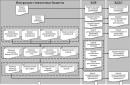
Device RDUK2 has the following features. The pressure regulator is formed by two units - a control unit (actuator) and a control unit (command control unit, the so-called “pilot”). The type of pilot is selected based on the required output pressure that the regulator must provide. Based on this principle, there are models with a low pressure pilot KN2 (0.005–0.6 kgf/cm2) and a high pressure pilot KV2 (0.6–6 kgf/cm2).
The operation of the device is carried out using the energy of the working environment and is carried out as follows. A reduction in gas pressure in the RDUK regulator occurs as a result of moving the equipped rubber seal poppet plunger in relation to the valve seat. This movement is carried out under the influence of the difference between the inlet pressure on the plate and the outlet pressure acting from below.
The high-pressure gas that has overcome the filter is supplied to the small valve of the pilot unit and after it into the sub-membrane space of the control valve. Excess gas from under the control valve membrane is discharged back into the gas pipeline through a relief throttle.
Pulses of output pressure are applied to the membranes of the pilot and actuator, which is always lower than the input. Depending on the gas flow and the inlet pressure, the pressure under the membrane is constantly monitored by the small valve of the pilot device in automatic mode are being adjusted. When the pressure at the outlet of the RDU changes relative to a given value in the submembrane space, the pressure will also change, which will lead to the movement of the main valve to a new equilibrium position and the return of the outlet pressure to the required level.
How to buy a gas pressure regulator RDUK
Before you buy a pressure regulator RDUK2, it is worth choosing the optimal modification of the device based on the parameters required by the customer: output pressure, seat diameter and nominal bore (DN). For example, the RDUK regulator with a design of DN 50 has a saddle of 35 mm, DN 100 - 50 and 70 mm (low and high pressure, respectively), DN 200 - a saddle of 105 and 140 mm (low and high pressure, respectively). How larger size seats, the greater the throughput capacity of the modifications of the Kazantsev gas pressure regulator.
You can check the availability of the modification of the RDUK regulator you are interested in, its current cost or other information of interest about the products presented on our website from the managers of the PKF SpetsKomplektPribor company. You can submit a request for the supply of the required number of regulators at any time in a convenient way– by phone, Skype or email.
Manufacturer: LLC PF "Gazservis"
Specifications
| Regulator type | Operating pressure | Overall dimensions, mm | Weight, kg | |
| Input P 1, MPa | Output P 2, kPa | |||
| RDUK2-50/35N | 0,6 | 0,6-60 | 230 x 320 x 300 | 45 |
| RDUK2-50/35V | 1,2 | 60-600 | -»- | -»- |
| RDUK2-100/50N |
1,2
|
0,5-60 | 350 x 464 x 418 | 92 |
| RDUK2-100/50V | 1,2 | 60-600 | -»- | -»- |
| RDUK2-100/70N | 1,2 | 0,5-60 | -»- | -»- |
| RDUK2-100/70V | 1,2 | 60-600 | -»- | -»- |
| RDUK2-200/105N | 1,2 | 0,5-60 | 600 x 650 x 711 | 282 |
| RDUK2-200/105V | 1,2 | 60-600 | -»- | -»- |
| RDUK2-200/140N | 0,6 | 0,5-60 | -»- | -»- |
| RDUK2-200/140V | 1,2 | 60-600 | -»- | -»- |
Note. First digit after letter designation type of regulator - diameter of the connecting pipe D y, the second - diameter of the valve seat, mm.
The maximum throughput of RDUK2 regulators is shown in Fig. 4.25-4.29, where P 1, P 2 are the inlet and outlet pressure, respectively, kg/cm2.
Ambient temperature - from -30 to +45 °C.
Design and principle of operation
In the circuit of the pressure regulator RDUK2 (Fig. 4.23, 4.24), the control regulator KN2 low and KV2 high pressure is a command device, and the control valve is an actuator. The operation of the pressure regulator is carried out using the energy of the passing working medium.
The inlet pressure gas, in addition to the main valve, flows through the filter to the small valve of the control regulator and then through the connecting tube through the damping throttle - under the control valve membrane. Gas is discharged into the gas pipeline behind the pressure regulator through a relief choke.

Rice. 4.23. Longitudinal section and connection diagram of the RDUK2-100 regulator. (Control regulator and connection points impulse tubes to the membrane chamber are conventionally rotated by 90°)

Rice. 4.24. Longitudinal section and connection diagram of RDUK2-200 regulators. (The control regulator and the connection points of the impulse tubes to the membrane chamber are conventionally rotated by 90°)
Output gas pressure is supplied to the membranes of the control valve and control regulator through connecting tubes. Due to the continuous flow of gas through the relief orifice, the pressure upstream of it and therefore below the control valve diaphragm is always greater than the outlet pressure.
The pressure difference on both sides of the control valve membrane forms the lifting force of the membrane, which, under any steady state operating mode of the regulator, is balanced by the weight of the moving parts and the action of the inlet pressure on the main valve.
The increased pressure under the control valve diaphragm is automatically regulated by the small valve of the control regulator, depending on the gas consumption and the inlet pressure before the regulator.
The output pressure force on the control regulator membrane is constantly compared with the force of the lower spring specified during adjustment; any slight deviation in output pressure causes the diaphragm and control valve to move. This changes the flow of gas passing through the small valve, and therefore the pressure under the control valve membrane.
Thus, for any deviation of the outlet pressure from the set point, the change in pressure under the large membrane causes the main valve to move to a new equilibrium position, at which the outlet pressure is restored. For example, if, as gas consumption decreases, the outlet pressure increases, the diaphragm and valve of the control regulator will lower slightly. In this case, the gas flow through the small valve will decrease, which will cause a decrease in pressure under the control valve membrane. The main valve, under the influence of inlet pressure, will begin to close until its flow area corresponds to the new gas consumption and the outlet pressure is restored.

Rice. 4.25. Graph of maximum capacity of regulators RDUK2N-50/35 and RDUK2V-50/35

Rice. 4.26. Graph of maximum capacity of regulators RDUK2N-100/50 and RDUK2V-100/50

Rice. 4.27. Graph of maximum capacity of regulators RDUK2N-100/70 and RDUK2V-100/70

Rice. 4.28. Graph of maximum capacity of regulators RDUK2N-200/105 and RDUK2V-200/105

Rice. 4.29. Graph of maximum capacity of regulators RDUK2N-200/140 and RDUK2V-200/140

Rice. 4.30. Control regulator KH2
During operation, the stroke of the diaphragm and valve of the control regulator required for full speed the main valve is very small, and the change in the forces of both springs at this small stroke, as well as the effect of the changing inlet pressure on the small valve, constitute an insignificant part of the effect of the outlet pressure on the control regulator diaphragm. This means that the regulator, with changes in gas consumption and inlet pressure, maintains the outlet pressure due to a slight deviation from the set one. In practice, these deviations are approximately 1-5% of the nominal value.
To overcome a certain weight of the moving parts of the control valve when it opens and the resistance of the small valve to the gas flow, a minimum pressure drop of 300 mm water is required. Art.
Type: universal pressure regulator.
The RDUK-2-50 regulator is designed to reduce gas pressure and automatically maintain a given outlet pressure and installation in gas control points (GRP), gas control units (GRU).
The regulator provides a reduction in gas inlet pressure and automatically maintains a set outlet pressure regardless of changes in gas flow and inlet pressure.
The RDUK-2-50 gas regulator is used in gas supply systems for industrial, agricultural and municipal facilities.
Basic technical data of the RDUK-2-50 regulator
Type: universal gas pressure regulator.
Climatic version: U2 GOST 15150-69.
Ambient temperature: from minus 45 to plus 40 0 C.
Weight: 15 kg.
| Name of parameter or size | RDUK-2N-50 | RDUK-2V-50 |
| Nominal diameter of the inlet flange, DN mm | 50 | 50 |
| Seat diameter, mm | 25 | 35 |
| Maximum input pressure, MPa (kgf/cm2) | 1,2 (12) | 1,2 (12) |
| Output pressure setting range, MPa (kgf/cm2) | 0,005—0,06 (0,005—0,6) | 0,06—0,6 (0,6—6,0) |
| Maximum throughput, m 3 / h | 6000 | 6000 |
Design and principle of operation of the RDUK-2-50 regulator
Overall dimensions of the gas pressure regulator RDUK-2-50
| Regulator type | construction length, mm | width, mm | height, mm |
| RDUK-2N-50 | 230 | 466 | 278 |
| RDUK-2V-50 | 230 | 466 | 278 |
The gas pressure regulator RDUK-2-50 consists of two main components - control valve 5 and pilot 20. A diaphragm drive is attached to the lower part of the housing. The pusher 6 rests against the central seat of the plate, and the valve stem 7 rests against it, transmitting the vertical movement of the membrane plate 3 to the regulator valve. The rod moves in the guide column of the housing 4; a valve with a rubber seal 8 sits freely on the upper end of the rod. The housing is closed on top with a lid.
The KN-2 or KV-2 pilot plays the role of a command device in the pressure regulator piping circuit. The pilot consists of a housing 11, a cover 12, a membrane 15 sandwiched between them, a valve 21, a tuning spring 14 and an adjusting cup 13.
The inlet pressure gas enters the pilot from the top of the housing. After throttling in the pilot, gas through tube 17 enters the sub-membrane space of the control valve through a calibrated hole into damping throttle 1. Excess gas from the sub-membrane space is constantly discharged into the gas pipeline after the regulator through tube 18 through a throttle installed on the gas pipeline. Appropriate selection of the diameters of the throttles 1 and the throttle on the gas pipeline in the presence of a continuous gas flow through tubes 17 and 18 makes it possible to constantly maintain a pressure slightly higher than the output pressure in the sub-membrane space of the control valve. This pressure difference on both sides of the membrane 3 forms its lifting force, which is balanced at any steady state of operation of the regulator by the weight of the moving parts and the action of the inlet pressure on the valve 8.
The compression of the pilot spring 14, which determines the value of the gas outlet pressure, is carried out by screwing in the adjusting cup 13. The greater the outlet pressure should be, the more the spring should be compressed. When the regulator is not operating, the spring must be weakened.
With an increase in gas extraction from the gas pipeline, its pressure after the regulator and under the membrane of pilot 15 and the control valve will decrease. The pilot membrane, under the action of the spring 14, will lower and, through the pusher 10, press on the pilot valve 21, compressing the spring 9 located above it. The pilot seat will open slightly more, the flow of gas into the sub-diaphragm space of the control valve and its pressure from below on the membrane 3 will increase. The membrane, rising, will increase the valve lift and gas flow through the regulator.
As gas extraction from the gas pipeline decreases, its pressure after the regulator and under the membrane of pilot 15 and the control valve will increase. The pilot diaphragm will rise and block the flow of gas through the pilot valve into the sub-diaphragm space of the control valve. The gas pressure under the membrane 3, as a result of its discharge through the tube 18, will decrease, and the membrane, under the influence of the increasing pressure of the gas above it, will drop, and the control valve will reduce the gas supply through the regulator.
The pressure difference on both sides of the membrane creates a lifting force of the membrane, which, in any steady state operation of the control regulator, is balanced by the weight of the moving parts and the inlet gas pressure on the valve.
When the outlet gas pressure decreases, the pressure in the space above the membrane will also increase, while in the space below the membrane it will not change. As a result, the membrane rises and opens the valve.
As the outlet gas pressure increases, the pressure in the space above the membrane will also increase, while in the space below the membrane it will not change. As a result, the membrane will lower and close the valve. Thus, for any deviation of the output pressure from the set one, the change in pressure in the space above the membrane will cause the valve to move to a new equilibrium position, at which the output pressure will be restored.
Indication of safety measures when working with the pressure regulator RDUK-2-50
The RDUK-2-50 regulator must be installed on gas pipelines with pressures corresponding to those specified in the technical specifications.
Installation and switching on of the RDUK-2-50-2 pressure regulator must be carried out by a specialized construction, installation and operational organization in accordance with the approved project, technical specifications for construction and installation work, “safety rules in the gas industry.”
Elimination of defects when inspecting regulators should be carried out without pressure.
During testing, the increase and decrease in pressure should be carried out smoothly.
Preparing the pressure regulator RDUK-2-50 for operation
Before starting the pressure regulator, the following steps must be carried out: General requirements training and safety precautions provided for in the instructions for starting a gas control point or gas control installation.
Placement and installation of the RDUK-2-50 regulator
The pressure regulator RDUK-2-50-2 is mounted on a horizontal section.
The connection of the impulse pipeline 19 and tubes 16 and 18 from the membrane chamber to the main gas pipeline can be carried out in various ways:
The impulse tube 19 is connected to the middle of a straight section of the gas pipeline after the regulator with a length of ≈10 of its diameters. The total length of the tube should not exceed 6 m. Tubes 16 and 18 are connected to the gas pipeline after the regulator in a section of ≈100 mm in length.
Pulse tube 19 is connected to the middle part of the straight section of the hydraulic fracturing bypass, tubes 16 and 18 are connected to the gas pipeline after the regulator in a section ≈100 mm long.
Tubes 19, 16 and 18 are connected to a special pipe, which is welded to the gas pipeline after the regulator at a distance of at least 5 of its diameters from the nearest turn.
Before starting, the adjusting screw of the control regulator (pilot) must be turned out until the spring is completely weakened.
For low pressure regulator it is necessary to check the installation replaceable spring to the required range of adjustable outlet pressure.
Operating procedure.
When the pilot spring is completely weakened, the regulator is started by gradually screwing in the pilot adjusting cup.
The required gas outlet pressure is set using a pressure gauge.
For stable operation of the regulator during startup, it is recommended to ensure a minimum gas flow after it to the purge plug.
To create flow through the regulator, it is advisable to use not the candle closest to the regulator, but the one farthest (if there is more than one candle). In this case, the regulator is adjusted to a more difficult operating mode.
After the spark plug there should not be a section of the gas pipeline that is closed during setup and startup. In this case, it acts as a gas accumulator, which negatively affects the adjustment conditions of the regulator and can lead to fluctuations in gas pressure during adjustment.
Maintenance of regulator RDUK-2-50
The RDUK-2-50 regulator is subject to technical condition inspection and routine repairs according to the approved schedule in accordance with the requirements of PB-12-529-03.
Inspection of technical condition is carried out as follows:
To inspect the RDUK-2-50-2 control valve, it is necessary to remove the top cover, the valve with the stem and clean them. The valve seat and guide bushings should be thoroughly wiped. The sealing edge of the seat should be carefully inspected. If there are nicks or deep scratches, the seat should be replaced. The valve stem must move freely in the column. To inspect the membrane, you must remove the bottom cover. The membrane must be wiped.
Typical malfunctions of RDUK-2-50 gas pressure regulators and methods for eliminating them
Violation of the operating mode of the RDUK-2-50-2 regulator during operation most often occurs when the main valve stem gets stuck, as well as when the chokes on the regulator piping pipes become clogged.
The pilot spring is completely weakened, but the output pressure increases. The reason is a leak in the main valve. The solution is to replace the valve.
The outlet pressure drops to zero. The reason is a membrane rupture. Replace the membrane.
The outlet pressure fluctuates greatly at low gas flow rates, regardless of the set pressure. It can be eliminated by installing a throttle control valve with a diameter of 3, 4 or 6 mm, respectively, for regulators DN 50, 100, 200 mm on pipe 16 to the above-membrane cavity. If vibration elimination cannot be achieved by installing a throttle on the tube, then reduce the inlet pressure and, if necessary, replace the seat and valve with smaller sizes.