In order to facilitate the installation of electrical wiring, all cable and wire products have appropriate multi-colored markings. As a rule, in houses or apartments, lighting is installed and sockets are connected using three wires. Each of them has its own purpose in the home electrical network. Therefore, the designation of the color of the ground wires has great importance. Due to this, installation time and subsequent repairs are significantly reduced. Thanks to color coding, any type of connection is not particularly difficult.
Ground wire
In most cases, yellow is used to indicate the ground wire. green color. Sometimes you can find conductors with insulation only yellow color. Even less commonly used is light green. Typically, such wires are marked with PE symbols. However, if the ground wire is aligned with the neutral, it is designated as PEN. It is colored green-yellow and has a blue braid at the ends.
In the distribution panel, the grounding wire is connected to a special busbar, or to the housing and metal door. IN distribution box the connection is made with similar wires provided in lamps and sockets equipped with special grounding contacts. The grounding wire does not need to be connected to a residual current device (RCD), so such protective devices are used where only two wires are used for electrical wiring.
Neutral conductor (neutral)
The color blue is traditionally used for the neutral conductor or neutral. The connection in the distribution panel is made through a special zero bus, designated by the symbol N. All blue wires are connected to this bus.

The bus itself is connected to the input via. In some cases, the connection can be made directly, without any additional automatic devices.
All neutral wires in the junction box of blue color are connected together and do not take part in commutation. The exception is the wire coming from the switch. Connecting blue wires to sockets is done using a special zero contact, designated by the letter N. This marking is affixed to the reverse side of each socket.
Phase wire color
The phase does not have any precise designation. Black, brown, red and other colors other than green, yellow and blue are quite common. In the distribution panel installed in the apartment, the connection of the phase wire coming from the consumer is made with the contact of the circuit breaker located below. In other circuits, this conductor may be connected to a residual current device.

In switches, the phase is directly involved in switching. With its help, the contact is closed and opened - turned on and off. In this way, voltage is supplied to consumers, and, if necessary, this supply is stopped. In sockets, the phase conductor is connected to the contact marked L.
Wire Definition
Sometimes situations arise when it is necessary to determine the purpose of a particular wire if there is no marking on it. The simplest and most common way is. With its help, you can accurately determine which wire will be phase and which will be neutral. First of all, you need to turn off the power supply to the panel. After this, the ends of the two conductors are stripped and separated to the sides away from each other. Then you need to turn on the electricity supply and use the indicator to determine the purpose of each wire. If the light bulb lights up upon contact with the core, this is a phase. This means the other core will be neutral.

If there is a ground wire in the electrical wiring, it is recommended to use a multimeter. This device is equipped with two tentacles. First the measurement is established alternating current in the range of more than 220 volts at the corresponding mark. One tentacle is fixed at the end of the phase wire, and the second one determines grounding or zero. In case of contact with zero, the device display will display a voltage of 220 volts. When you touch the ground wire, the voltage will be noticeably lower.
Marking
There is not only the color of the wires phase, zero, ground, but also other types of markings, primarily alphabetic and digital designations. The first letter A indicates the wire material - aluminum. If this letter is missing, the core material will be copper.
Basic marking of wires in electrical engineering:
- AA - corresponds to stranded aluminum cable with additional braiding made of the same material.
- AC - additional lead braid.
- B - the presence of protection from moisture and additional braiding made of two-layer steel.
- BN - non-flammable cable braid.
- G - absence of a protective shell.
- R - rubber shell.
- HP - rubber shell made of non-flammable material.
Very few people understand the essence of electricity. Concepts such as “electric current”, “voltage”, “phase” and “zero” are a dark forest for most, although we encounter them every day. Let's get a grain of useful knowledge and figure out what phase and zero are in electricity. To teach electricity from scratch, we need to understand the fundamental concepts. We are primarily interested in electric current and electric charge.
Electric current and electric charge
Electric charge is a physical scalar quantity that determines the ability of bodies to be a source of electromagnetic fields. The carrier of the smallest or elementary electric charge is the electron. Its charge is approximately -1.6 to 10 to the minus nineteenth power of Coulomb.
Electron charge is the minimum electrical charge (quantum, portion of charge) that occurs in nature in free, long-lived particles.
Charges are conventionally divided into positive and negative. For example, if we rub an ebonite stick on wool, it will acquire a negative electrical charge (excess electrons that were captured by the atoms of the stick upon contact with the wool).
Static electricity on hair has the same nature, only in this case the charge is positive (hair loses electrons).
The main type of alternating current is sinusoidal current . This is a current that first increases in one direction, reaches a maximum (amplitude), begins to decrease, at some point becomes equal to zero and increases again, but in a different direction.

Directly about the mysterious phase and zero
We have all heard about phase, three phases, zero and grounding.
The simplest case electrical circuit – single phase circuit . It only has three wires. Through one of the wires the current flows to the consumer (let it be an iron or hair dryer), and through the other it returns back. Third wire in single-phase network– ground (or grounding).
The ground wire does not carry a load, but serves as a fuse. In case something gets out of control, grounding helps prevent electric shock. This wire carries excess electricity or “drains” into the ground.
The wire through which current flows to the device is called phase , and the wire through which the current returns is zero.
So, why do we need zero in electricity? Yes, for the same thing as the phase! The current flows through the phase wire to the consumer, and through the neutral wire it is discharged in the opposite direction. The network through which alternating current is distributed is three-phase. It consists of three phase wires and one return.
It is through this network that the current flows to our apartments. Approaching directly to the consumer (apartments), the current is divided into phases, and each phase is given a zero. The frequency of changing the direction of current in the CIS countries is 50 Hz.
IN different countries There are different standards for voltages and frequencies in the network. For example, a typical household outlet in the United States supplies alternating current with a voltage of 100-127 Volts and a frequency of 60 Hertz.
The phase and neutral wires should not be confused. Otherwise, you can cause a short circuit in the circuit. To prevent this from happening and to prevent you from confusing anything, the wires have acquired different colors.
What color are phase and zero indicated in electricity? Zero is usually blue or cyan, and phase is white, black or brown. The ground wire also has its own color - yellow-green.

So, today we learned what the concepts of “phase” and “zero” mean in electricity. We will be simply happy if this information was new and interesting for someone. Now, when you hear something about electricity, phase, zero and ground, you will already know what it is about we're talking about. Finally, we remind you that if you suddenly need to calculate a three-phase AC circuit, you can safely contact . With the help of our specialists, even the wildest and difficult task it will be tough for you.
In order to correctly read and understand what a particular diagram or drawing related to electricity means, you need to know how the icons and symbols depicted on them are deciphered. A large number of information contain letter designations elements in electrical diagrams, defined by various regulatory documents. All of them are displayed in Latin characters in the form of one or two letters.
One-letter symbolism of elements
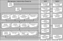
Letter codes corresponding to individual types of elements most widely used in electrical circuits are combined into groups designated by one symbol. Letter designations correspond to GOST 2.710-81. For example, the letter “A” refers to the “Device” group, consisting of lasers, amplifiers, remote control devices and others.
The group denoted by the symbol “B” is deciphered in the same way. It consists of devices that convert non-electrical quantities into electrical ones, which does not include generators and power supplies. This group is complemented by analogue or multi-digit converters, as well as sensors for indications or measurements. The components themselves included in the group are represented by microphones, loudspeakers, sound pickups, ionizing radiation detectors, thermoelectric sensitive elements, etc.
All letter designations corresponding to the most common elements are combined into a special table for ease of use:
|
The first letter character required to be reflected in the marking |
Group of main types of elements and devices |
Elements that make up the group (the most typical examples) |
|
|
Devices |
Lasers, masers, remote control devices, amplifiers. |
||
|
Equipment for converting non-electrical quantities into electrical ones (without generators and power supplies), analogue and multi-charge converters, sensors for indications or measurements |
Microphones, loudspeakers, sound pickups, ionizing radiation detectors, sensitive thermoelectric elements. |
||
|
Capacitors |
|||
|
Microassemblies, integrated circuits |
Digital and analog integrated circuits, memory and delay devices, logic elements. |
||
|
Miscellaneous elements |
Different kinds lighting devices and heating elements. |
||
|
Designation of the fuse on the diagram, arresters, protective devices |
Fuses, arresters, discrete current and voltage protection elements. |
||
|
Power supplies, generators, crystal oscillators |
Rechargeable batteries, power supplies on an electrochemical and electrothermal basis. |
||
|
Signal and indication devices |
Indicators, light and sound signaling devices |
||
|
Contactors, relays, starters |
Voltage and current relays, time relays, electrothermal relays, magnetic starters, contactors. |
||
|
Chokes, inductors |
Chokes in fluorescent lighting. |
||
|
Engines |
DC and AC motors. |
||
|
Measuring instruments and equipment |
Counters, clocks, indicating, recording and measuring instruments. |
||
|
Power circuit breakers, short circuiters, disconnectors. |
|||
|
Resistors |
|||
|
Pulse counters |
|||
|
Frequency meters |
|||
|
Active energy meters |
|||
|
Reactive energy meters |
|||
|
Recording devices |
|||
|
Action time meters, clocks |
|||
|
Voltmeters |
|||
|
Wattmeters |
|||
|
Switches and disconnectors in power circuits |
Circuit breakers |
||
|
Short circuits |
|||
|
Disconnectors |
|||
|
Resistors |
Thermistors |
||
|
Potentiometers |
|||
|
Measuring shunts |
|||
|
Varistors |
|||
|
Switching devices in measurement, control and signaling circuits |
Switches and switches |
||
|
Push-button switches |
|||
|
Automatic switches |
|||
|
Switches triggered by various factors: From level |
|||
|
From pressure |
|||
|
From position (travel) |
|||
|
From rotation speed |
|||
|
From temperature |
|||
|
Transformers, autotransformers |
Current transformers |
||
|
Electromagnetic stabilizers |
|||
|
Voltage transformers |
|||
|
Communication devices, converters of non-electrical quantities into electrical ones |
Modulators |
||
|
Demodulators |
|||
|
Discriminators |
|||
|
Frequency generators, inverters, frequency converters |
|||
|
Semiconductor and electrovacuum devices |
Diodes, zener diodes |
||
|
Electrovacuum devices |
|||
|
Transistors |
|||
|
Thyristors |
|||
|
Antennas, lines and microwave elements |
Couplers |
||
|
Short circuits |
|||
|
Transformers, phase shifters |
|||
|
Attenuators |
|||
|
Contact connections |
Sliding contacts, current collectors |
||
|
Separable connections |
|||
|
High Frequency Connectors |
|||
|
Mechanical devices with electromagnetic drive |
Electromagnets |
||
|
Brakes with electromagnetic drives |
|||
|
Clutches with electromagnetic drives |
|||
|
Electromagnetic cartridges or plates |
|||
|
Limiters, terminal devices, filters |
Limiters |
||
|
Quartz filters |
In addition, GOST 2.710-81 defines Special symbols to indicate each element.
Conventional graphic symbols of electronic components in circuits
And in everyday life we use, as a rule, single-phase. This is achieved by connecting our wiring to one of the three phase wires (Figure 1), and for further consideration of the material, which phase comes into the apartment is completely indifferent to us. Since this example is very schematic, we should briefly consider the physical meaning of such a connection (Figure 2).
Electric current occurs in the presence of a closed electrical circuit, which consists of the winding (Lt) of the substation transformer (1), the connecting line (2), and the electrical wiring of our apartment (3). (Here the designation of phase is L, zero - N).
Another point - in order for current to flow through this circuit, at least one electricity consumer Rн must be turned on in the apartment. Otherwise, there will be no current, but the VOLTAGE on the phase will remain.
One of the ends of the Lt winding at the substation is grounded, that is, it has electrical contact with the ground (Zml). The wire that comes from this point is neutral, the other is phase.
This leads to another obvious practical conclusion: the voltage between “zero” and “ground” will be close to zero (determined by grounding resistance), and “ground” will be “phase”, in our case 220 Volts.
Moreover, if hypothetically ( In practice this cannot be done!) ground the neutral wire in the apartment, disconnecting it from the substation (Fig. 3), the voltage “phase” - “zero” will be the same 220 Volts.
We figured out what phase and zero are. Let's talk about grounding. I think its physical meaning is already clear, so I suggest looking at it with practical point vision.

If, for some reason, electrical contact occurs between the phase and the conductive (metal, for example) body of an electrical device, voltage appears on the latter.
When you touch this body, an electric current may flow through the body. This is due to the presence of electrical contact between the body and the “ground” (Fig. 4). How less resistance this contact (wet or metal floor, direct contact building structure with natural grounding conductors (heating radiators, metal water pipes) the greater the danger you face.
The solution to this problem is to ground the housing (Figure 5), in which case the dangerous current will “disappear” through the grounding circuit.
Structurally, the implementation of this method of protection against electric shock for apartments, office premises consists of laying a separate PE grounding conductor (Fig. 6), which is subsequently grounded in one way or another.
How this is done is a topic for a separate discussion; for example, in a private house you can make a grounding loop yourself. Exist various options with their own advantages and disadvantages, but for further understanding of this material they are not fundamental, since I propose to consider several purely practical issues.
HOW TO DETERMINE PHASE AND ZERO
Where is the phase, where is the zero - a question that arises when connecting any electrical device.
First let's look at how to find phase. The easiest way to do this is with an indicator screwdriver (Figure 7).

With the conductive tip of the indicator screwdriver (1) we touch the controlled section of the electrical circuit (during operation, contact of this part of the screwdriver with the body is unacceptable!), with a finger we touch contact pad 3, the glow of indicator 2 indicates the presence of a phase.
In addition to an indicator screwdriver, the phase can be checked with a multimeter (tester), although this is more labor-intensive. To do this, the multimeter should be switched to AC voltage measurement mode with a limit of more than 220 Volts. With one probe of the multimeter (it doesn’t matter which one) we touch the section of the circuit being measured, with the other we touch the natural ground electrode (heating radiators, metal water pipes). When the multimeter readings correspond to the network voltage (about 220 V), there is a phase in the measured section of the circuit (diagram Fig. 8).

I draw your attention to the fact that if the measurements taken show the absence of a phase, it cannot be stated that this is zero. Example in Figure 9.
- Now there is no phase 1 at point.
- When the switch S is closed, it appears.
Therefore, you should check all possible options.
I would like to note that if there is a grounding wire in the electrical wiring, it is impossible to distinguish it from the neutral conductor using electrical measurements within the apartment. As a rule, the wire used for grounding is yellow-green in color, but it is better to verify this visually, for example, remove the socket cover and see which wire is connected to the grounding contacts.
© 2012-2019 All rights reserved.
All materials presented on this site are for informational purposes only and cannot be used as guidelines or regulatory documents.
World manufacturers household appliances When assembling their equipment, they use color coding for the mounting wires. It represents the designation in electrics L and N. Thanks to a strictly defined color, the master can quickly determine which of the wires is phase, neutral or ground. This is important when connecting or disconnecting equipment from power.
Types of wires
When connecting electrical equipment and installing various systems, you cannot do without special conductors. They are made of aluminum or copper. These materials conduct electricity well.
Important! Aluminum wires must only be connected to aluminum wires. They are chemically active. If they are connected to copper, the current transmission circuit will quickly collapse. They are usually connected using nuts and bolts. Copper - through a terminal. It is worth considering that the latter type of conductors has a significant drawback - it quickly oxidizes when exposed to air.

Advice in case the current stops flowing at the site of oxidation: To restore the power supply, the wire must be insulated from external influences using electrical tape.
Wire classification
The conductor consists of one uninsulated or one or more insulated conductors. The second type of conductors is covered with a special non-metallic sheath. This can be a winding with insulating tape or a braid made of fibrous raw materials. Bare wires have no protective coatings. They are used in the construction of power lines.
Based on the above, we conclude that the wires are:
- protected;
- unprotected;
- power;
- installation.
They must be used strictly for their intended purpose. The slightest deviation from operating requirements leads to a breakdown of the power supply network. As a result of the short circuit, fires occur.

Designations of phase, neutral and ground wires
When installing electrical networks for domestic and industrial purposes, insulated cables are used. They consist of many conductive wires. Each of them is painted in a corresponding color. The designations LO, L, N in electrics allow you to reduce the time for installation and, if necessary, repair work.
The electrical designation L and N described below fully complies with the requirements of GOST R 50462 and is used in electrical installations in which the voltage reaches 1000 V. They have Electrical equipment of all residential, administrative buildings, and commercial facilities. What color designations for phase L, zero, N and grounding must be observed when installing electrical networks? Let's figure it out.
Phase conductors
The AC network contains conductors that are energized. They are called phase wires. Translated from in English The term "phase" means "line", "active wire", or "live wire".
Human contact with a phase wire exposed from insulation can result in serious burns or even death. What does the electrical designation L and N mean? On electrical diagrams, phase wires are marked Latin letter“L”, and in multi-core cables the insulation of the phase wire will be painted in one of the following colors:
- white;
- black;
- brown;
- red.
Recommendations! If for any reason an electrician doubts the veracity of the information displaying the color marking of the cable wires, a low-voltage tester must be used to determine which wire is live.

Neutral conductors
These electrical wires are divided into three categories:
- zero working conductors.
- neutral protective (ground) conductors.
- combining protective and working functions.
To determine which of the conductors is phase and which is neutral using an indicator screwdriver, you need to touch the uninsulated part of the wire with its tip. If the LED lights up, it means that a phase conductor has been touched. After touching the neutral wire with a screwdriver, there will be no glowing effect.
Importance color coding conductors and strict adherence to the rules of its use will significantly reduce the time of conducting installation work and troubleshooting electrical equipment, while ignoring these basic requirements results in a health risk.