To relieve gas downstream of the regulator in the event of a short-term increase in gas pressure above the set value, safety relief valves (PSVs) must be used.
PSK is a valve that is closed in operational condition; it opens for a short period of time, and after reaching the nominal pressure at the controlled point, it automatically closes.
PSC can be spring or membrane.
Spring-loaded valves must be equipped with a device for their forced opening and control purging in order to prevent sticking, freezing and sticking of the spool to the seat, as well as to remove solid particles trapped between the sealing surfaces.
PSKs are divided into full-lift and low-lift. For low-lift valves (PSK type), the valve opens gradually, in proportion to the increase in pressure at the controlled point of the gas pipeline. Full-lift valves (SPPKR4R-16) open completely and sharply, with a jerk, and just as sharply, with the spool hitting the seat, they close when the pressure decreases. That is, the full-lift valve has a two-position position: closed and open. When the maximum permissible setting pressure is reached, the PSK valve must open without fail until it is fully raised, in open position work steadily.
The valve must close when the pressure drops to the nominal pressure or below it by 5% and ensure tightness. If there is a delay in closing the valve, the gas pressure in the network may drop significantly, which can lead to disruption of the system’s operating mode, as well as the release of relatively large quantity gas For low-lift PSKs, when closing the shutter after resetting The spool performs the functions of both a sensing element and a shut-off element, whereas in diaphragm valves the spool performs only shut-off functions. The membrane makes it possible to increase the sensitivity of PSCs in general and expand the range of their use, including low gas pressure. PSK must ensure opening when the established operating pressure is exceeded by no more than 15%.
The choice of UCS design should be made in accordance with the throughput.
The amount of gas to be discharged by the PSK should be determined:
If there is a SSV in front of the pressure regulator according to the formula Q≥0.0005Qd, where Q is the amount of gas to be discharged by the SSV within an hour at t=0° C and Pbar=0.10132 MPa, m³/h; Qd - design capacity of the pressure regulator at t=0° C and Pbar=0.10132 MPa, m³/h;
in the absence of a slam-shut valve in front of the pressure regulator according to the formulas: for pressure regulators with a seat valve Q≥0.01Qd, for control valves Q≥0.02Qd.
Low-lift membrane and spring PSKs have a small throughput. Thus, the throughput capacity of SPPK4R-50-16 (seat diameter 30 mm) at an operating pressure of 0.125 MPa is 830 m³/h, and PSK-50S/125 (seat diameter 50 mm) is only 10 m³/h. This is explained by the low lifting height of the spool. The capacity of PSK-50 (KPS-50) valves with guide ribs at low pressure is: 0.5–3 m³/h, at average - 7–20 m³/h (at a pressure in the PSK inlet pipe of 1.15 set pressure) .
Bandwidth PSK-50 without guide ribs can be taken twice as large with the same parameters. In addition to these PSCs, relief valves can also be part (component) of combined gas pressure regulators.
To relieve gas downstream of the regulator in the event of a short-term increase in gas pressure above the set value, safety relief valves (PSVs) must be used. PSK is a valve that is closed in operational condition; it opens for a short period of time, and after the pressure at the controlled point reaches the nominal value, it automatically closes.
PSC can be spring or membrane. Spring-loaded valves must be equipped with a device for their forced opening and control purging in order to prevent sticking, freezing and sticking of the spool to the seat, as well as to remove solid particles trapped between the sealing surfaces.
PSKs are divided into full-lift and low-lift. For low-lift valves (PSK type), the valve opens gradually, in proportion to the increase in pressure at the controlled point of the gas pipeline. Full-lift valves (SPPKR4R-16) open completely and sharply, with a jerk, and just as sharply, with the spool hitting the seat, they close when the pressure decreases. That is, a full-lift valve has a two-position position: “closed” and “open”.
When the maximum permissible setting pressure is reached, the PSK valve must open without fail to full lift and operate stably in the open position. The valve must close when the pressure drops to the nominal pressure or below it by 5% and ensure tightness. If there is a delay in closing the valve, the gas pressure in the network may drop significantly, which can lead to disruption of the system operation, as well as the release of a relatively large amount of gas into the atmosphere.
For low-lift PSKs, when closing the valve after releasing the required amount of gas, it is difficult to achieve sealing of the valve, since this may require applying more force than in the “closed” mode.
Such PSCs stop releasing gas only after the pressure decreases to 0.8-0.85% of the operating pressure, which leads to a constant or long-term release of gas into the atmosphere. The main advantage of membrane PSCs is the presence in their design of an elastic membrane that acts as a sensitive element. If in spring valves the spool performs the functions of both a sensing element and a shut-off element, then in diaphragm valves the spool performs only shut-off functions. The membrane makes it possible to increase the sensitivity of PSCs in general and expand the range of their use, including low gas pressure. PSCs must ensure opening when the established operating pressure is exceeded by no more than 15%.
The choice of UCS design should be made in accordance with the throughput.
The amount of gas to be discharged by the PSK should be determined:
- if there is a SCP in front of the pressure regulator according to the formula Q≥0.0005Q d, where Q is the amount of gas to be discharged by the SCP within an hour at t = 0 °C and P bar = 0.10132 MPa, m 3 / h; Q d - design capacity of the pressure regulator at t = 0 °C and P bar = 0.10132 MPa, m 3 / h;
- in the absence of a slam-shut valve in front of the pressure regulator according to the formulas: for pressure regulators with a seat valve - Q≥0.01Q d, for control valves - Q≥0.02Q d.
Low-lift membrane and spring PSKs have a small throughput. Thus, the throughput capacity of SPPK4R-50-16 (seat diameter 30 mm) at an operating pressure of 0.125 MPa is 830 m3/h, and PSK-50S/125 (seat diameter 50 mm) is only 10 m3/h. This is explained by the low lifting height of the spool. The throughput capacity of PSK-50 (KPS-50) valves with guide ribs at low pressure is: 0.5-3 m3/h, at average - 7-20 m3/h (at a pressure in the PSK inlet pipe of 1.15 set pressure) .
The throughput capacity of PSK-50 without guide ribs with the same parameters can be assumed to be twice as large.
The table (page 1245) shows the main specifications serially produced PSK. In addition to these PSCs, relief valves can also be part (component) of combined gas pressure regulators.
Safety relief valves PSK 25 are membrane-type devices and are designed to discharge gas into the atmosphere when the pressure (in the network or tank) increases above the permissible limit and are installed on gas pipelines and gas control stations of low, medium and high pressure.
Connection to the pipeline is coupling (GOST 6357) or flange.
PSK valves with conditional passage DN 25
are produced in several types:
- relief valves low pressure triggering – PSK-25-P-N;
- high pressure relief valves - PSK-25-P-V.
Relief valves PSK 25 - technical characteristics:
| Name | Conditional pass | Regulation limit, kPa | Bandwidth |
| PSK-25-P-N | 25 mm | 2,0 -0,1 - 75,0 +7,5 | not less than 120 m 3 / h |
| PSK-25-P-V | 25 mm | 60,0 -6,0 - 750,0 +75,0 | not less than 1000 m 3 / h |

Relief valves PSK 25 - technical parameters:
| Parameter | PSK-25 | PSK-25F |
| Nominal diameter, DN, mm | 25 (1"") | 25 (1"") |
| Valve setting range | from 2 to 750 kPa | from 2 to 750 kPa |
| Housing material | aluminum AK 7h | aluminum AK 7h |
| Working environment | natural gas GOST 5542 |
natural gas GOST 5542 |
| Ambient temperature | from -40 o C to +45 o C | from -40 o C to +45 o C |
| dimensions, no more: - D, mm - H, mm - A, mm - V, mm |
160 210 80 30 |
200 250 120 70 |
| Product weight, no more | 2.34 kg | 4.85 kg |
RELIEF VALVES PSK-50
 Safety relief valves PSK 50 are membrane-type devices and are designed to discharge gas into the atmosphere when the pressure (in the network or tank) increases above the permissible limit and are installed on gas pipelines and gas control stations of low, medium and high pressure. Connection to the pipeline is coupling (GOST 6357) or flange.
PSK valves with nominal bore DN 50 are produced in several types:
- low pressure relief valves - PSK-50P-N/20;
- relief valves with medium response pressure – PSK-50-P-S/50;
- relief valves with medium response pressure – PSK-50-P-S/125;
- high pressure relief valves – PSK-50-P-V/1000.
Relief valves PSK 50 - technical characteristics:
| Name | Conditional pass | Regulation limit, kPa | Bandwidth |
| PSK-50P-N/20 | 50 mm | 2,0 -0,1 - 20,0 +2,0 | not less than 200 m 3 / h |
| PSK-50P-S/50 | 50 mm | 20,0 -2,0 - 50,0 +5,0 | not less than 440 m 3 / h |
| PSK-50P-S/12 5 | 50 mm | 50,0 -5,0 - 125,0 +12,5 | not less than 1100 m 3 / h |
| PSK-50P-V/1000 | 50 mm | 125,0 -12,5 - 1000,0 +100 | not less than 5600 m 3 / h |
Relief valves PSK 50 - technical parameters:
| Parameter | PSK-50 (coupled) | PSK-50F (flange) |
| Nominal diameter, DN, mm | 50 (2"") | 50 (2"") |
| Valve setting range | from 2 to 1000 kPa | from 2 to 1000 kPa |
| Housing material | aluminum AK 7h | aluminum AK 7h |
| Working environment | natural gas GOST 5542 |
natural gas GOST 5542 |
| Ambient temperature | from -40 o C to +45 o C | from -40 o C to +45 o C |
| Overall dimensions, no more: - D, mm - N, mm - Ah, mm - V, mm |
220 240 88 43 |
260 300 149 104 |
| Product weight, no more | 4.25 kg | 10.04 kg |
VALVE DEVICE
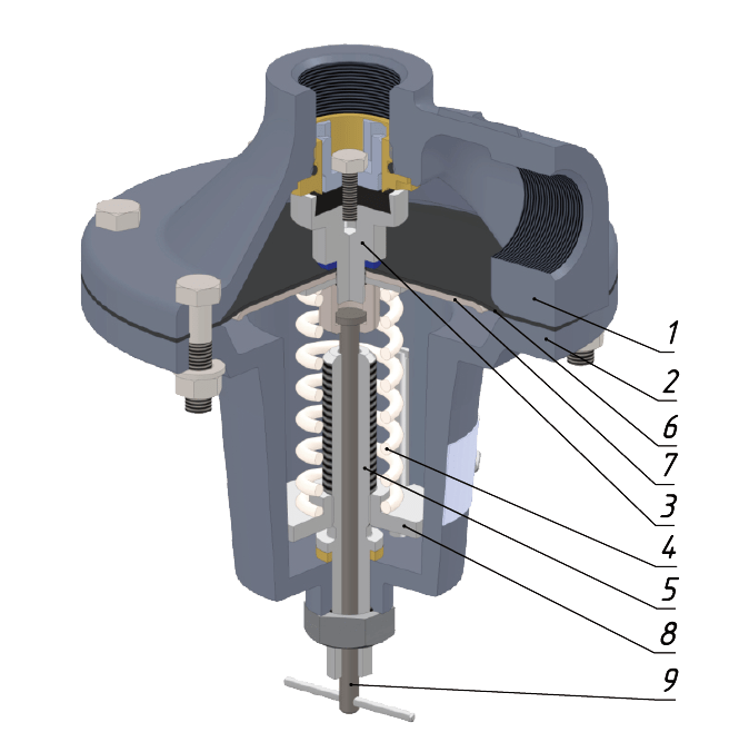
The appearance of PSK type valves is shown in the figure.The valve body is made in the form of a truncated cone with a flange, a seat and two holes with cylindrical pipe threads 1 inch - version PSK-25P, 2 inches - version PSK-50P or with metric thread M36x1.5 - version PSK-25PF and M56x2 - version PSK-50PF. The seat is closed by valve pos. 3 with rubber seal. The valve is assembled with a membrane pos. 6, which is rigidly fixed between the valve and the plate pos. 7. In turn, the membrane is fixed between the body, pos. 1 and cover pos. 2.
Spring pos. 4 is sandwiched between the membrane plate and the stop pos. 8. By rotating the adjusting screw pos. 5 the stop pos. moves. 8, thus changing the force of the spring, which determines the setting of the valve to pressure within specified limits.
To check the functionality, the valve is equipped with a forced opening mechanism, which is activated by the rod pos. 9.

VALVE OPERATING PRINCIPLE
Gas from the network enters the valve cavity through the inlet of the housing.In steady state, the controlled gas pressure within the set limits is balanced by the adjusted spring, and the valve is hermetically closed.
When the gas pressure in the network (also in the valve cavity) exceeds the setting limit, the membrane, overcoming the forces of the spring, drops along with the valve, opening the gas outlet to the atmosphere through the discharge pipe.
The gas will be released until the pressure in the network drops below the set value, after which the valve will close under the action of the spring.
To check the functionality of the valve, pull the rod of the forced opening mechanism. The valve opens. Repeat the operation 3 – 4 times.
PRICE, PRODUCTION TIME, DELIVERY CONDITIONS
The price for valves PSK-25 and PSK-50 is provided upon official request to our company. The production time for relief valves does not exceed 20 days. Delivery is carried out to all regions of the Russian Federation, as well as to the territory of the CIS countries by any means of transport.The warranty period is 36 months from the date of commissioning of the product, but not more than 48 months from the date of manufacture.
The designated service life of the valve is 35 years.
Safety relief valves PSK are designed for automatic release of gas into the atmosphere when pressure rises above set values.
Working medium – natural gas according to GOST 5542-2014. Working environment temperature from minus 10 to plus 40ºС. The valve seal tightness is class A according to GOST 9544-2015.
The valves are used in gas distribution and gas consumption systems.
The operating conditions of PSK valves must comply with climatic version U3 according to GOST 15150-69 (limit operating air temperature values from minus 40 to + 45 C).
Valves are manufactured with nominal bore DN 25 and DN 50, low, medium and high response pressure.
Type of connection to the gas pipeline:
- internal pipe thread according to GOST 6357-81;
- flanged according to GOST 33259-2015.
The valve is equipped with a device for forced purging. The high energy efficiency of the valve is determined by its design - there are no gas losses during operation.
PSK valves prevent an increase in gas pressure after the regulator to eliminate false operation shut-off valve. This is usually observed in the system during transient conditions or when there is no gas consumption.
At the enterprise LLC PKF "EX-FORM" relief valves PSK
are produced according to TU 3712-008-12213528-2011.
PSK valves are available in several types:
With nominal diameter DN 25:
- low pressure relief valves - PSK-25 P-N
- high pressure relief valves - PSK-25 P-V.
With nominal diameter DN 50:
- low pressure relief valves – PSK-50P-N/20
- relief valves with medium response pressure – PSK-50P-S/50
- relief valves with medium response pressure – PSK-50P-S/125
- high pressure relief valves - PSK-50P-V/1000
Technical characteristics of PSK valves
| Execution | DN | Range settings, kPa |
Passport ability, max m 3 /h |
Weight |
| PSK-25PN | 2 – 75 | 21 | 3 kg | |
| PSK-25PV | 60 – 750 | 124 | 3 kg | |
| PSK-25N/5 | 2 – 5 | 16,5 | 3 kg | |
| PSK-25S/20 | 5 – 20 | 56 | 3 kg | |
| PSK-25S/50 | 20 – 50 | 44 | 3 kg | |
| PSK-25S/125 | 50 – 125 | 231 | 3 kg | |
| PSK-25S/300 | 125 – 300 | 345 | 3 kg | |
| PSK-25V/700 | 300 – 700 | 623 | 3 kg | |
| PSK-50PN/20 | 2 – 20 | 14,5 | 4.5 kg | |
| PSK-50PS/50 | 20 – 50 | 74 | 4.5 kg | |
| PSK-50PS/125 | 50 – 125 | 170 | 4.5 kg | |
| PSK-50PV/1000 | 125 – 1000 | 268 | 4.5 kg | |
| PSK-50N/5 | 2 – 5 | 79 | 4.5 kg | |
| PSK-50S/20 | 5 – 20 | 83 | 4.5 kg | |
| PSK-50S/50 | 20 – 50 | 108 | 4.5 kg | |
| PSK-50S/125 | 50 – 125 | 464 | 4.5 kg | |
| PSK-50S/300 | 125 – 300 | 354 | 4.5 kg | |
| PSK-50V/700 | 300 – 700 | 635 | 4.5 kg | |
| PSK-25PFN | 2 – 75 | 21 | 5.5 kg | |
| PSK-25PFV | 60 – 750 | 124 | 5.5 kg | |
| PSK-25FN/5 | 2 – 5 | 16,5 | 5.5 kg | |
| PSK-25FS/20 | 5 – 20 | 56 | 5.5 kg | |
| PSK-25FS/50 | 20 – 50 | 44 | 5.5 kg | |
| PSK-25FS/125 | 50 – 125 | 231 | 5.5 kg | |
| PSK-25FS/300 | 125 – 300 | 345 | 5.5 kg | |
| PSK-25FV/700 | 300 – 700 | 623 | 5.5 kg | |
| PSK-50PFN/20 | 2 – 20 | 14,5 | 10 kg | |
| PSK-50PFS/50 | 20 – 50 | 74 | 10 kg | |
| PSK-50PFS/125 | 50 – 125 | 170 | 10 kg | |
| PSK-50PFV/1000 | 125 – 1000 | 268 | 10 kg | |
| PSK-50FN/5 | 2 – 5 | 79 | 10 kg | |
| PSK-50FS/20 | 5 – 20 | 83 | 10 kg | |
| PSK-50FS/50 | 20 – 50 | 108 | 10 kg | |
| PSK-50FS/125 | 50 – 125 | 464 | 10 kg | |
| PSK-50FS/300 | 125 – 300 | 354 | 10 kg | |
| PSK-50FV/700 | 300 – 700 | 635 | 10 kg |
Closing pressure: 0.9 R setting
The assigned service life of the valves is 35 years, subject to timely replacement during operation of parts and components that have a shorter, naturally limited service life (for sealing gaskets, rings - 5 years, for membranes - 5 years, for springs - 10 years ).
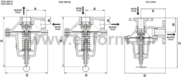
Overall dimensions of PSK-25

Overall dimensions of PSK-50

PSK Valve Design
The valve body is made in the form of a truncated cone with a flange, a seat and two holes with cylindrical pipe threads 1 inch - version PSK-25P, 2 inches - version PSK-50P or with metric thread M36x1.5 - version PSK-25PF and M56x2 - version PSK -50PF.
The seat is closed by valve pos. 3 with rubber seal. The valve is assembled with a membrane pos. 6, which is rigidly fixed between the valve and the plate pos. 7. In turn, the membrane is fixed between the body, pos. 1 and cover pos. 2.
Spring pos. 4 is sandwiched between the membrane plate and the stop pos. 8. By rotating the adjusting screw pos. 5 the stop pos. moves. 8, thus changing the force of the spring, which determines the setting of the valve to pressure within specified limits.
To check the functionality, the valve is equipped with a forced opening mechanism, which is activated by the rod pos. 9.
Preparing and putting the product into operation
The valve is installed in such a way that the direction of movement of the medium coincides with the direction of the arrow on the product body, or according to letter designation indicated on the product body.The valve in front of the PSK must be open and sealed. All connections of the gas pipeline fittings during the installation of the PSK are checked for leaks. Gas leaks through leaky connections are not allowed.
It is necessary to install the low response pressure PSK (marked with the letter H) into the working position with the lid down. PSK medium and high pressure settings (marked with the letters “C” and “B”) can be installed in any position.
To check the functionality of the valve, pull the rod of the forced opening mechanism (pos. 9). The valve opens. Repeat the operation 3 – 4 times.
The valve is turned on by rotating the adjusting screw (item 5) to the desired response parameters. The screw is easily accessible. The screw rotates easily, without jamming.
A safe complete stop of the Valve operation is carried out by closing the tap installed in front of the Valve.
Operating principle of the valve
Gas from the network enters the valve cavity through the inlet of the housing.In steady state, the controlled gas pressure within the set limits is balanced by the adjusted spring, and the valve is hermetically closed.
When the gas pressure in the network (also in the valve cavity) exceeds the setting limit, the membrane, overcoming the forces of the spring, drops along with the valve, opening the gas outlet to the atmosphere through the discharge pipe.
The gas will be released until the pressure in the network drops below the set value, after which the valve will close under the action of the spring.
Price, production time, delivery conditions
The price of PSK valves is provided upon official request to our company. The production time for relief valves does not exceed 20 days. Warehouse stocks are also available. Delivery is carried out to all regions of the Russian Federation, as well as to the territory of the CIS countries by any means of transport.The warranty period is 36 months from the date of commissioning of the product, but not more than 42 months from the date of manufacture.
The designated service life of the valve is 35 years.
By special order of the consumer, the valves can be adjusted to a given response pressure in accordance with a specific order or technical specifications and sealed.
Characteristics
Description
| Name of parameter or size | Magnitude |
|---|---|
| 1 Nominal diameter, mm | 50 |
| 2 Maximum valve opening pressure, kPa (kgf/cm 2) | |
| PSK-50N/5 | 5(0,05) |
| PSK-50S/20 | 20(0,2) |
| PSK-50S/50 | 50(0,5) |
| PSK-50S/125 | 125(1,25) |
| PSK-50V/400 | 400 (4) |
| PSK-50V/700 | 700 (7) |
| 3 Response setting range, kPa | |
| PSK-50N/5 | from 2 to 5 |
| PSK-50S/20 | from 5 to 20 |
| PSK-50S/50 | from 20 to 50 |
| PSK-50S/125 | from 50 to 125 |
| PSK-50V/400 | from 125 to 400 |
| PSK-50V/700 | from 400 to 700 |
| 4 Valve tightness class | B according to GOST 9544-2005 |
| 5 Connecting dimensions: at the inlet and outlet, internal pipe thread according to GOST 6357-81, inches | 2 |
| 6 Overall dimensions, mm, no more | |
| - diameter | 220 |
| - height | 255 |
| 7 Weight, kg, no more | 5,0 |
Note: The safety relief valve setting should be 1.15 working pressure.
Average service life, years, not less than 15;
Designated service life, years, not less than 40.
Purpose of the product
Safety relief valves PSK are designed to limit the pressure of non-aggressive gases by releasing the gas into the atmosphere to a set value when the pressure in the network increases above the permissible limit.
The valves are installed on low, medium and high pressure gas pipelines, as well as at regulatory stations.
The operating conditions of the valves correspond to the climatic version UHL2 GOST 15150-69 with an ambient temperature from minus 40 to plus 60° C.
The valves do not have a negative impact on the environment during operation.
Design and principle of operation
The safety relief valve PSK-50 consists of a body 1 (see Figure 1), a cover 2, a valve 3 with a guide and rubber seal, spring 4 and adjusting screw 5, membrane 6, plate 7 and spring plate 8.
Housing 1 is made in the form of a truncated cone, with a flange, a seat and two holes with a 2" thread. The seat is closed by valve 3 with a rubber seal. The valve is assembled with a membrane 6, which is fixed between the body flange and the cover 2.
Spring 4 is clamped between the membrane plates and the adjusting screw 5. By rotating the adjusting screw, the spring plate 8 moves, thus changing the force of the spring, which determines the valve response pressure setting.
Gas from the network enters the supravalvular cavity through the inlet of the housing.
In steady state, the controlled gas pressure within the established limits is balanced by the adjusted spring and the valve is hermetically closed.
When the gas pressure in the network (above the valve) exceeds the setting limit, the valve, overcoming the spring force, opens, allowing gas to escape into the atmosphere.
The gas discharge will continue until the pressure in the network drops below the set value, after which the valve will close under the action of the spring.

1- body; 2 – cover; 3 – valve with guide and rubber seal; 4 – spring; 5 – adjusting screw;
6 – membrane; 7 – plate; 8 – spring plate.
Figure 1. Safety relief valve PSK-50N

1– body; 2 – cover; 3 – valve with guide and rubber seal; 4 – spring; 5 – adjusting screw; 6 – membrane; 7 – plate; 8 – spring plate.
Figure 2. Safety relief valve PSK-50V