It will be useful for novice home craftsmen to learn about methods for joining wooden parts. We are devoting a short educational program to this topic, which will describe the main types of carpentry joints and joints using glue, nails, screws or dowels, or without them at all.
Rules for selecting a connection depending on the type of load
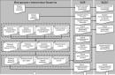
End connections are the simplest; they are used when it is necessary to extend a part. Such connections best withstand compression loads, however, when cutting locks of a special shape, good resistance to twisting, stretching and bending can be achieved. Standard option end connection - with trimming to half the thickness of both parts. The cut can be straight or oblique; if necessary, to prevent bending, stretching or twisting, a spike or an obtuse angle is cut at the end of each cut, or a stepped cut is made, forming a kind of “lock”.
 1 - straight half-wood overlay; 2 — oblique pad; 3 - straight overlay with a stepped joint; 4 — half-timber overlay with an oblique joint; 5 — oblique patch lock; 6 - half-tree connection with an oblique tenon
Corner and side joints are used to connect straight parts into a truss or frame. Usually this part of the structure is supporting, so the main loads occur in displacement and compression. If the structure is experiencing a static intended load, a rectangular tenon is cut on one of the parts, and a groove or eye of appropriate dimensions is cut on the other. If action on breaking the structure is possible, the tenon and groove are cut in the shape of a trapezoid.
 Corner connections: 1 - with an open through tenon; 2 - with a blind closed tenon; 3 - with a through oblique tenon
Overhead cross and T-shaped connections are used, as a rule, for additional connections between critical structural parts. The main load in them is compression, displacement and rupture. The first two types of load are eliminated by cutting half a tree or less, followed by combining the parts. The shoulders of the notches take the main load; all that remains is to secure the connection with screws or overhead staples. In some cases, to strengthen the connection, a dowel is used or a tenon with a wedge is cut out.
 1 - cross connection with a half-wood overlay; 2 — cross connection with fit into one socket; 3 - T-shaped connection with a hidden oblique tenon; 4 - T-shaped connection with a straight stepped overlay
A separate type of connection is box connection. They are intended for connecting boards at right angles. Typically, for a box joint, teeth are cut on each board, the width of which is equal to the distance between them. On different boards, the teeth are cut offset, so when connected, the corner of the boards looks like one whole. The teeth can also be wedge-shaped, preventing the corner from breaking in one direction, or they can be additionally secured with glue or nails.
 Box corner joints: 1 - with straight through tenons; 2 - with oblique through spikes
How to make a tenon joint
To make a tenon joint, you need to outline both parts with a marking line along all edges at a distance from the end equal to the width of the joint. On two opposite sides and the end, the body of the tenon is marked with lines; the markings on both parts are completely identical.
The tenon is cut from the sides with a hacksaw for a cross cut and the wood is chopped using a chisel. The width of the tenon is made 2-3 mm larger for subsequent precise processing with a knife or chisel. The groove is cut with a hacksaw for a longitudinal cut and chipped with a chisel, also leaving a small allowance for processing. Next comes the fitting, during which the parts are combined and the tightest fit is achieved.

With a T-shaped tenon joint, a central tenon or groove is cut on one of the parts, and an eye is hollowed out on the other, or two side cuts are made, depending on the type of the first part. To make an eye, use a chisel, turning the inclined part of the blade into the hole. If the eye is not solid, I make the tenon 8-10 mm deeper and cut off its end in the shape of an expanded wedge. This way, when driving, the tenon will open itself and the part will be firmly seated.
To connect wide parts, you can use a box connection by cutting several tenons and grooves. The easiest way to secure a tenon joint is to drill through it across the tenons and drive a wooden dowel (window corner joint) into the hole.

How to join boards with glue
A very popular method of joining boards and bars is longitudinal and transverse gluing. When connecting boards with the wide side, the end can be smooth, although in most cases a tongue-and-groove profile is used. It is very important to tightly fit the parts so that the glue layer is as thin as possible, this is the only way to achieve maximum strength. Sometimes a small amount of cotton fiber is applied to the end, lubricated with glue, this improves the quality of the coupling.

The boards can also be joined in profile, but this will require wedge-shaped gear cutting of both ends with the teeth offset to the floor for different parts. At home, this operation can be performed using a hand router.

To glue the parts together, casein glue or high concentration PVA is used; to give strength, sifted wood flour is added to the adhesive. The surfaces are covered with glue and kept in air for 3-5 minutes, after which they are placed under pressure or squeezed with clamps. This connection is stronger than the wood itself and never breaks at the joint.
How to connect elements of load-bearing structures
For load-bearing structures Two types of connections are used - extension and articulation. The easiest way to join two parts is to make a half-thick cut with a hacksaw at the same distance from the ends, and then chop off the excess wood with an ax. Once the two pieces are aligned, the joint is usually secured with two flashing strips nailed to the side of the cut. Gluing is also possible, but only if the parts fit tightly.

The ends cut into half a tree can be brought together at almost any angle; this is the main method of joining roof trusses. To fasten the parts, an additional tightening tie is required: the timber is applied to the connected parts from the side at a distance of 30-50 cm from the corner and cut to half the thickness at the points of contact, and then the structure is fastened with nails.

Often vertical and inclined structures need support, for example when connecting a rafter system to floor beams. In this case, the landing slots are cut on the horizontal beam into which the racks will be inserted. It is very important to maintain the angle of inclination and cut no more than a third of the thickness of the timber.

Connections with special connections
Almost all carpentry joints are made with additional reinforcing ties. In the very simple example the role of these is played by nails or screws.
When building up parts, the assembly can be strengthened with a through bolted connection, clamps, staples and capercaillie, or it can simply be wrapped with cold-rolled wire. It is enough to fasten the spliced vertical supports with two overhead strips - wooden or metal.

Corner joints are most often secured with staples, overlay plates or angles. In cases where it is necessary to maintain a slight mobility of the connection, use one through bolt, which either stitches across the place where the parts are overlayed, or tightens them in the longitudinal direction with a minimum distance from the overlay.

The place where the special connection is attached must be removed from the edge by at least 10 diameters of the fastening element and have no defects. It is important to remember that often ties do not provide the overall strength of the connection, but only compensate for the unaccounted load.
In addition to processing whole pieces wood, often have to be joined wooden parts into units and structures. Element connections wooden structures called landings. Joints in the structures of wooden parts are determined by five types of fits: tense, tight, sliding, loose and very loose fit.
Nodes - these are parts of structures at the junction of parts. Wooden structure connections are divided into types: end, side, corner T-shaped, cross-shaped, corner L-shaped and box corner connections.
Joinery joints have more than 200 options. Here we consider only the connections that joiners and carpenters use in practice.
End connection (extension) - connection of parts along the length, when one element is a continuation of the other. Such connections are smooth, jagged with spikes. Additionally, they are secured with glue, screws, and overlays. Horizontal end connections withstand compressive, tensile and bending loads (Fig. 1 - 5). Lumber is increased in length, forming vertical and horizontal toothed joints (wedge lock) at the ends (Fig. 6). Such joints do not need to be under pressure during the entire gluing process, since there are significant frictional forces at work. Toothed connections of lumber made by milling meet the first class of accuracy.
Connections of wooden structures must be made carefully, in accordance with three accuracy classes. The first class is for measuring instruments High Quality, the second class is for furniture products, and the third is for construction parts, agricultural implements and containers. The lateral connection by the edge of several boards or slats is called joining (Fig. 7). Such connections are used in the construction of floors, gates, carpentry doors, etc. Plank and slatted panels are additionally reinforced with crossbars and tips. When covering ceilings and walls, the upper boards overlap the lower ones by 1/5 - 1/4 of the width. The outer walls are sheathed with horizontally laid overlapping boards (Fig. 7, g). The upper board overlaps the lower one by 1/5 - 1/4 of the width, which ensures the removal of precipitation. Connecting the end of a part to the middle part of another forms a T-shaped connection of parts. Such connections have big number options, two of which are shown in Fig. 8. These connections (ties) are used when connecting joists of floors and partitions with the piping of a house. Connecting parts at right or oblique angles is called a cross connection. This connection has one or two grooves (Fig. 3.9). Cross joints are used in roof and truss structures.
 |
| Rice. 1. End connections of beams that resist compression: a - with a direct half-wood overlay; b - with an oblique overlay (on the “mustache”); c - with a straight half-wood overlay with a joint at an obtuse angle; g - with an oblique overlay with a tenon joint. |
 |
| Rice. 2. End connections of beams (extension) that resist tension: a - in a straight overhead lock; b - c oblique patch lock; c - with a straight half-timber overlay with a joint in an oblique tenon (c dovetail). |
 |
| Rice. 3. End connections of beams that resist bending: a - with a straight half-timber overlay with an oblique joint; b - with a straight half-timber overlay with a stepped joint; c - in an oblique overhead lock with wedges and a tenon joint. |
 |
| Rice. 4. Joining by cutting with reinforcement with wedges and bolts. |
 |
| Rice. 5. End connections of beams working in compression: a - end-to-end with a secret hollowed-out tenon; b - end-to-end with a hidden insert tenon; c - with a direct half-wood overlay (the connection can be strengthened with bolts); Mr. direct half-wood overlay secured with wire; d - with a straight half-wood overlay secured with metal clips (clamps); e - with an oblique overlay (on a “mustache”) secured with metal clips; g - with an oblique overlay and fastening with bolts; h - marking of the oblique overlay; and - end-to-end with a hidden tetrahedral tenon. |
 |
| Rice. 6. End extensions of the milling scheme during end gluing of workpieces: a - vertical (along the width of the part), toothed (wedge-shaped) connection; b - horizontal (according to the thickness of the part), toothed (wedge-shaped) connection; c - milling of a gear connection; d - sawing out a gear connection; d - milling of a gear connection; e - end connection and gluing. |
 |
| Rice. 7. Joining the boards: a - on a smooth reveal; b - on the insert rail; c - a quarter; g, e, f - in the groove and ridge (with various forms groove and tongue); g - overlap; h - with a tip in a groove; and - with a quarter tip; k - with overlap. |
 |
| Rice. 8. T-shaped connections of bars: a - with a hidden oblique tenon (in the paw or in the dovetail); b - with a straight stepped overlay. |
 |
| Rice. 9. Cross connections of bars: a - with a direct half-wood overlay; b - with direct overlay of incomplete overlap; in - with fit in one nest |
Connections of two parts with ends at right angles are called corner connections. They have through and non-through tenons, open and in the dark, half-dark on the overlay, half-tree, etc. (Fig. 10). Corner joints (ties) are used in window blocks, in joints of greenhouse frames, etc. A tenon joint in the dark has a tenon length of at least half the width of the part being connected, and the depth of the groove is 2 - 3 mm greater than the length of the tenon. This is necessary so that the parts to be joined can easily mate with each other, and there is room in the tenon socket after gluing for excess glue. For door frames, a corner tenon joint is used in the dark, and to increase the size of the connected surface, a semi-dark joint is used. Double or triple tenons increase the strength of the corner joint. However, the strength of the connection is determined by the quality of its execution. In furniture production, various corner box joints are widely used (Fig. 11). Of these, the simplest is an open end-to-end tenon connection. Before making such a connection, tenons are marked at one end of the board with an awl according to the drawing. By marking the side parts of the tenon with a file with fine teeth make a cut. Every second cut of the tenon is hollowed out with a chisel. To make the connection precise, first saw and hollow out the tenon sockets in one part. It is placed on the end of another part and crushed. Then they saw through, hollow out and connect the parts, cleaning the joint with a plane, as shown in Fig. eleven.
When connecting parts “mustache” (at an angle of 45°), the corner binding is secured with steel inserts, as shown in Fig. 12. At the same time, make sure that one half of the insert or fastener fits into one part, and the other half into another. A wedge-shaped steel plate or ring is placed in the milled grooves of the parts to be connected.
The corners of the frames and drawers are connected with a straight open through tenon joint (Fig. 3.13, a, b, c). With increased quality requirements (with outside the tenons are not visible) corner knitting is performed with an oblique connection in the dark, groove and tongue, or an oblique connection to the rail, as shown in Fig. 13, d, e, f, g and in Fig. 14.
A box-shaped structure with horizontal or vertical transverse elements (shelves, partitions) is connected using corner T-shaped joints shown in Fig. 15.
Corner notches are used to connect the elements of the upper chord of wooden trusses with the lower one. When connecting truss elements at an angle of 45° or less, one notch is made in the lower element (tightening) (Fig. 16.a), at an angle of more than 45° - two notches (Fig. 16.6). In both cases, the end cut (cut) is perpendicular to the direction of the acting forces.
Additionally, the units are secured with a bolt with a washer and a nut, or less often with staples. The log walls of a house (log house) made of horizontally laid logs in the corners are connected by a “claw” notch. It can be simple or with an additional spike (paw with a pit). The marking of the cut is carried out as follows: the end of the log is hewn into a square, to the length of the side of the square (along the log), so that after processing it turns out to be a cube. The sides of the cube are divided into 8 equal parts. Then 4/8 of the part is removed from one side from the bottom and top, and the remaining sides are done as shown in Fig. 17. To speed up the marking and accuracy of making cuts, templates are used.
 |
| Rice. 10. Corner end connections of workpieces at right angles: a - with a single opening through tenon; b - with a single through hidden tenon (in the dark); v-s single a dull (not through) thorn in the dark; g - with a single through semi-secret tenon (semi-dark); d - with a single blind spike in semi-darkness; e - with a triple open through tenon; g - in a straight half-tree overlay; h - through dovetail; and - into the eyes with trimming. |
 |
| Rice. 11. Box corner joints with straight through tenons: a - cutting out tenon grooves; b - marking the spikes with an awl; c - connection of a tenon with a groove; d - processing the corner joint with a planer. |
 |
| Rice. 12. Corner end connections at right angles, reinforced with metal inserts - buttons: a - 8-shaped insert; b- wedge-shaped plate; c- rings. |
 |
| Rice. 13. Box corner joints at right angles: a - straight open through tenons; b - oblique open through spikes; c - open through spikes in a dovetail; g - groove on the insert rail butt; d - in groove and tongue; e - on plug-in spikes; g - on dovetail spikes in semi-darkness. |
 |
| Rice. 14. Oblique (mustache) box joints at right angles: a - with oblique tenons in the dark; b - oblique connection to the plug-in rail; c - oblique connection to tenons in the dark; d - an oblique connection, reinforced with a triangular strip on glue. |
 |
| Rice. 15. Direct and oblique connections of workpieces: a - for a double connection in an oblique groove and ridge; b - on a straight groove and ridge; c - on a triangular groove and ridge; d - on a straight groove and a ridge in the dark; d - for straight through tenons; e - on round inserted tenons in the dark; g - on a dovetail spike; h - on the groove and ridge, reinforced with nails. |
 |
| Rice. 16. Nodes in truss elements. |
 |
| Rice. 17. Interfacing the logs of the log house walls: a - a simple paw; b - paw with a wind spike; c - marking of the paw; 1 - wind spike (pit) |
All photos from the article
Sometimes, when carrying out construction and other work using wood, it is necessary to make elements longer or wider, but very few people know how to do this correctly. That is why we will look at how to splice boards yourself and what methods and techniques exist. It is important to choose the option that is best suited in a given situation and requires minimal investment of time and money.

Basic workflow requirements
Before we begin to consider specific options for carrying out work, it is necessary to understand what factors will ensure that we obtain the expected result:
| Material quality | Everything is simple here: it is impossible to make it from low-quality wood. durable structures, this is especially true for joints; if they have knots, damage from woodworms, mold and other problems, then there can be no talk of any reliability or durability. Select the best elements so as not to waste effort and money |
| Humidity | Another the most important parameter, which should always be taken into account. Only dry elements are suitable for work, since high humidity, firstly, it reduces strength, secondly, it reduces the adhesion of the adhesive composition when using it, and thirdly, after completion of the work, no one will guarantee that in a week or month the structure will not move or it will not crack |
| Connection Loads | The choice of one or another connection option largely depends on this indicator; the greater the load, the higher the requirements for the quality of the connection and the more complex the process. Therefore, decide in advance which option will be used to ensure a good result. |
| Using a quality tool | A lot also depends on this, especially when it comes to complex options when the connection is cut with special devices. They must ensure maximum cutting quality and maximum joining accuracy, since reliability largely depends on this |
Important!
Remember one simple rule that experts always use: to get the best result, the parameters of the elements being joined must be similar; in other words, the same type of wood must be used.
![]()
Work options
All events of this kind can be divided into two large groups– joining boards in width and length; we will look at them separately and tell you which techniques are the most popular and how to implement them correctly.
Width connection
Of course, the simplest solution would be a panel splice option, so we will start with it, first present a diagram of the main options, and below we will describe them in detail:

- The first method involves cutting out a cavity using a milling machine, which has a trapezoidal shape and allows the use of a key as a retainer.. The advantage of this solution can be called reliability, and the disadvantage is the need for milling machine or the presence of a manual milling cutter to carry out the work, hand tools you can't get by here;
- Joining using an end block, which is connected to the ends of the board using the tongue-and-groove method, is used for elements of short length, because this option ensures high reliability of small structures. Again you will need it for work. With its help, it will be carried out quickly and efficiently;
- You can make a cutout along the end, fit a strip under it and place it on wood glue, it's also quite interesting option, which is suitable for small-sized structures;
- The last two options involve gluing a triangular strip, only one of them cuts into the end, and the second option involves cutting the end at an angle, you need to choose what would be better suited in one situation or another.
But if you want to connect the board more securely, then one of the following methods will do:
- The first option is called a smooth joint, which requires very careful grinding of the ends for a tight fit, after which they are lubricated with glue and connected under a press or using special ties. This solution is suitable in cases where high load-bearing capacity is not needed;
- The traditional tongue-and-groove option is often used, here it is important to ensure the optimal configuration of the connection, so the width of the groove and, accordingly, the tongue should not be more than a third of the total thickness of the board, it is important to do the cutting very accurately so that the elements match perfectly, this will significantly increase the strength of the connection;
Important!
When working, a milling cutter is most often used, but cutters can have different configurations; you should monitor the condition of their cutting edges and sharpen or replace them in a timely manner, since the quality of the connection largely depends on the cleanliness of the processing.
- You can use the option of cutting at an angle; it is well suited where special strength is not required, but elements that can be used for finishing, etc. need to be well connected;
- The triangular tongue and groove is in many ways similar to a regular one, only the configuration of the ends differs. It is also important here that the elements fit perfectly together, as this will ensure both the accuracy of the pairing and its maximum reliability;
- The quarter connection is simple - cuts are made at half the thickness, the length of the protrusions should not greatly exceed the thickness, the elements are lubricated with glue and compressed until the composition dries, this is a standard procedure for almost all options;
- The last type is keyed joining, it does not differ from the option described above when carrying out work along the width, the requirements are the same.
Conclusion
Connecting the board correctly and securely means ensuring its maximum strength; it is important to follow all recommendations and use only quality materials. The video in this article will show some options for carrying out the work visually, and if you have questions or additions, please leave a comment.
Often during the construction of roof frames of complex configurations, there is a need to use elements custom size. Typical examples include hip and half-hip structures, the diagonal ribs of which are significantly longer than ordinary rafter legs.
Similar situations arise when constructing systems with valleys. To ensure that the created connections do not cause weakening of structures, you need to know how rafters are spliced along the length and how their strength is ensured.
Splicing the rafter legs allows you to unify the lumber purchased for constructing the roof. Knowledge of the intricacies of the process makes it possible to almost completely construct a rafter frame from a bar or board of the same section. The design of the system from materials of the same size has a beneficial effect on the total cost.
In addition, boards and bars of increased length, as a rule, are produced with a cross-section larger than that of the material standard sizes. Along with the cross-section, the cost also increases. Such a safety factor when installing hip and valley ribs is most often not needed. But if the rafter splicing is carried out correctly, the elements of the system are provided with sufficient rigidity and reliability at the lowest cost.
Without knowledge of technological nuances, it is quite difficult to make truly bending-stiff lumber joints. The connecting nodes of the rafters belong to the category of plastic hinges, which have only one degree of freedom - the ability to rotate in the connecting node when a vertical and compressive load along the length is applied.
In order to ensure uniform rigidity when bending force is applied along the entire length of the element, the junction of the two parts of the rafter leg is located in places with the lowest bending moment. In diagrams demonstrating the magnitude of the bending moment, they are clearly visible. These are the points of intersection of the curve with the longitudinal axis of the rafters, at which the bending moment approaches zero values.
Let us take into account that when constructing a rafter frame, it is necessary to ensure equal resistance to bending along the entire length of the element, and not equal opportunities to bend. Therefore, the interface points are located next to the supports.
Both the intermediate post installed in the span and the Mauerlat or truss truss itself are used as support. The ridge girder can also be assessed as a possible support, but the joining areas of the rafter legs are better located lower along the slope, i.e. where the minimum load is placed on the system.
Options for splicing rafters
Except precise definition where to connect the two parts of the system element, you need to know how the rafters are extended correctly. The method of forming the connection depends on the lumber chosen for construction:
- Bars or log. They are built up with an oblique cut formed in the joint area. To strengthen and to prevent rotation, the edges of both parts of the rafters, cut at an angle, are fastened with a bolt.
- Boards sewn together in pairs. Spliced with the arrangement of joining lines staggered. The connection of two overlapping parts is made with nails.
- Single board. The priority is splicing with a frontal stop - by joining the trimmed parts of the rafter leg with the application of one or a pair of wooden or metal overlays. Less commonly, due to the insufficient thickness of the material, an oblique cut with fastening with metal clamps or traditional nailing is used.
Let us consider these methods in detail in order to understand in depth the process of increasing the length of the rafters.
Option 1: Oblique cut method
The method involves the formation of two inclined notches or cuts arranged on the side where the parts of the rafter leg meet. The planes of the notches to be joined must be perfectly aligned without the slightest gap, regardless of their size. The possibility of deformation must be excluded in the connection area.
It is prohibited to fill cracks and leaks with wedges made of wood, plywood or metal plates. It will not be possible to adjust and correct flaws. It is better to accurately measure and draw cutting lines in advance, according to the following standards:
- The depth is determined by the formula 0.15 × h, where h denotes the height of the beam. This is the size of the area perpendicular to the longitudinal axis of the beam.
- The interval within which the inclined sections of the cutting are located is determined by the formula 2 × h.
The location for the joining section is found using the formula 0.15 × L, valid for all types of rafter frames, in which the L value reflects the size of the span covered by the rafters. The distance is measured from the center of the support.
Parts made of timber when making an oblique cut are additionally secured with a bolt passing through the center of the connection. The hole for its installation is drilled in advance; its Ø is equal to the Ø of the fastener rod. To prevent the wood from being crushed at the mounting location, wide metal washers are placed under the nuts.
If a board is connected using an oblique cut, then additional fixation is made using clamps or nails.
Option 2: Placing the boards together
When using bonding technology, the center of the connected area is located directly above the support. The joining lines of the trimmed boards are located on both sides of the center of the support at a calculated distance of 0.21 × L, where L denotes the length of the overlapped span. Fixation is carried out with nails installed in a checkerboard pattern.
Backlash and gaps are also unacceptable, but they are easier to avoid by carefully trimming the board. This method is much simpler to implement than the previous method, but in order not to waste hardware and not weaken the wood with unnecessary holes, you should accurately calculate the number of fastener points to be installed.
Nails with a stem cross-section up to 6 mm are installed without preliminary drilling of the corresponding holes. It is necessary to drill for fasteners larger than the specified size so as not to split the board along the fibers when connecting. The exception is hardware with a cross-section, which, regardless of size, can simply be hammered into wooden parts.
To ensure sufficient strength in the bonding zone, the following conditions must be met:
- Fasteners are placed every 50 cm along both edges of the boards being joined.
- Along the end connections, nails are placed in increments of 15 × d, where d is the diameter of the nail.
- Smooth round, screw and threaded nails are suitable for holding the board together at the joint. However, threaded and screw options are a priority, because their pull-out strength is much higher.
Note that connecting rafters by welding is acceptable if an element is constructed from two sewn boards. As a result, both joints are covered with a solid section of lumber. The advantages of this method include the size of the overlapped span, which is impressive for private construction. In a similar way, you can extend the rafter legs if the distance from the top to the bottom support reaches 6.5 m.
Option 3: Frontal rest
The method of frontal extension of rafters consists in the end joining of the connected parts of the rafter leg with fixation of the section with nails, dowels or bolts through linings installed on both side planes.
To avoid play and deformation of the extended rafter leg, you must adhere to the following rules:
- The edges of the boards to be joined must be perfectly trimmed. Gaps of any size along the connection line must be eliminated.
- The length of the pads is determined by the formula l = 3 × h, i.e. they must be no less than three times the width of the board. Usually the length is calculated and selected based on the number of nails; the formula is given to determine the minimum length.
- The overlays are made of material whose thickness is at least 1/3 of the same size as the main board.
Nails are driven into the linings in two parallel rows with a staggered “dispersion” of fastening points. To avoid damaging the overlay, which is thin in relation to the main lumber, the number of attachment points is calculated based on the resistance of the nails to the lateral force acting on the legs of the hardware.
When the junction of the rafter parts is located directly above the support, there is no need to calculate nailing to fix the linings. True, in this case the docked leg will begin to work as two separate beams both for deflection and compression, i.e. according to the normal scheme, you will have to calculate the load-bearing capacity for each of the component parts.
If steel rod bolts or rods without threads, dowels are used as fasteners when joining thick boards or timber, then the threat of deformation will be completely eliminated. In fact, even some gaps in the joining of the ends can be ignored, although it is still better to avoid such flaws.
When using screws or screws, pre-drill holes for their installation; the Ø of the holes is 2-3 mm less than the same size of the fastener leg.
When making frontal connections of rafters, it is necessary to strictly observe the design installation pitch, the number and diameter of fasteners. When the distances between fixation points are reduced, wood splitting may occur. If the holes for the fasteners are larger than the required dimensions, the rafters will be deformed, and if they are smaller, the lumber will split during the installation of the fasteners.
Extension with composite rafters
To connect and increase the length of the rafters there is still quite interesting way: extension using two boards. They are sewn to the side planes of the extended single element. Between the extended parts there remains a gap equal to the width of the top board.
The gap is filled with scraps of equal thickness, installed at intervals of no more than 7 × h, where h is the thickness of the board being extended. The length of spacer bars inserted into the lumen is at least 2 × h.
Extension using two extension boards is suitable for the following situations:
- The construction of a layered system along two side girders, which serve as a support for the location of the joining area of the main board with the attached elements.
- Installation of a diagonal rafter that defines the inclined edge of hip and half-hip structures.
- Construction of sloping roofs. The strapping of the lower tier of rafters is used as a support for the connection.
Calculation of fasteners, fixation of spacer bars and connection of boards is carried out by analogy with the methods described above. For the manufacture of spacer bars, trimmings from the main lumber are suitable. As a result of installing these liners, the strength of the prefabricated rafter significantly increases. Despite the significant savings in material, it works like a solid beam.
Video about ways to build rafters
Demonstration of basic splicing techniques structural elements rafter system:
A video with a step-by-step description of the process of connecting rafter parts:
Video example of one of the methods of joining lumber:
Compliance with the technological requirements according to which the rafters are spliced along the length guarantees trouble-free operation of the structure. Extension methods can reduce roof construction costs. You should not forget about preliminary calculations and preparation for making connections so that the result of your efforts becomes ideal.
What could it be easier connection wooden parts on a "mustache"? Despite the simplicity of the method, sometimes difficulties arise with the accuracy and precision of connections. In this article we will give you simple tips, by adopting which, you will achieve incredible results. Your corner joints will always be perfect!
1. Select the direction and structure of the fibers
It doesn’t matter what you are making: a photo frame or a frame for a furniture facade, make sure that the color of the wood, as well as the direction and structure of the fibers on the workpieces match. Selecting parts with similar structures takes a little time, but the result is excellent connections.
2. Fine-tune the cutting angle using sticky pieces of paper
If you've ever tried to adjust yours a few tenths of a degree, then you know how difficult it is to do so. We offer you an easy way to solve this problem: stick several sheets of note paper on the crossbar. Thus, by making test cuts and removing one sheet at a time, you will achieve the ideal cutting angle

3. Use scraps of blanks to try on parts
To accurately determine the length of the trim element, you need to try it on the panel. This is easy to do if you attach trim trim to the panel

4. Use dowels for smooth joints
It is often not easy to position the parts evenly relative to each other and clamp them in clamps, especially when the parts are lubricated with slippery glue. This is why woodworkers use dowels, even in cases where additional joint strength is not required.

5. Assemble frame structures using corner clamps
On some clamps, when assembling the frames, you need to additionally make sure that all corners are connected at 90 degrees. Using corner clamps There is no need for additional measurements of angles and setting diagonals.

6. Increase the open time of your glue
It can be difficult to quickly apply glue to the joints, assemble the frames, and clamp them into the clamps without rushing or fussing before the glue begins to set (often the open time of the glue is less than 5 minutes in a warm, dry room). To increase the open time of the glue, you can slightly dilute it with water. However, do not overdo it - if there is too much water, the strength of the connection may decrease.

7. First, assemble the parts “mustache”, then profile
It is not always convenient to trim profiled workpieces - chips may appear, they are not always easy to clamp in clamps - the outer profile of the product can be damaged. Therefore, simplify your life - first assemble and glue a frame from rectangular blanks, and after the glue has dried, profile it manual router or at

8. Trust your sense of touch.
When you make a frame design, the pieces on opposite sides of the product should be the same length. To verify this, perform a simple test. Place the two pieces together and run your finger along the ends. There should be no differences. You may not notice the difference in length by eye, but you will definitely feel even the slightest discrepancy in the length of the workpieces.

9. Close unsightly cracks
If during the process of assembling products you still were unable to avoid gaps at the corners of the joints, do not despair. Simply close them by pressing the corners into the center of the joint with a blunt, smooth object. You will be surprised, but the gap will disappear, and appearance the product will not deteriorate at all. Believe me, even experienced craftsmen use this method.

10. You can change the proportions of the product in case of an error
If the last part of your binding turns out to be slightly shorter than the opposite one, you can cut it along the inside. And after assembly, cut the remaining parts according outside. This will reduce the width of the strap slightly. If this is not for example furniture facade, then no one will notice anything