A do-it-yourself hydrogen burner is a completely feasible task for an experienced master and a beginner armed with detailed recommendations about her self-production. This device works thanks to the heat generated by hydrogen. A mixture of hydrogen and oxygen is a gas with the highest possible combustion temperature - 2800°C. It is called detonating gas or Brown's gas. However, you must be careful when working with this mixture as it is highly explosive.
Hydrogen has certain advantages over other flammable gases. For example, it can be obtained by electrolysis directly from water. A self-made hydrogen burner does not require the use of hydrogen in cylinders. The electrolysis burner is capable of supplying gas to the required quantities. Thanks to this, hydrogen welding is a very economical and safest method.
A homemade welding machine with a hydrogen torch can be made based on an electrolysis generator. The possibility of a gas explosion using such equipment is completely eliminated, since all the gas is immediately used for welding and does not accumulate in a quantity sufficient for an explosion.
What is required to make a burner?

To make a hydrogen burner, you need to stock up on the following materials:
- sheet stainless steel;
- 2 bolts M6x150 with nuts and washers;
- a transparent tube, for example, such as in a water level;
- fittings with outer diameter appropriate hose;
- sealed Plastic container volume 1.5 liters;
- small filter for purifying supply water;
- water check valve.
The choice of stainless steel must be approached responsibly. It is advisable to choose the brand of imported steel AISI 316L or the domestic equivalent - 03Х16Н15М3. However, if there is a small piece of stainless steel 50x50 cm with a thickness of 2 mm, then there is no need to purchase a whole sheet.
It is necessary to use stainless steel, since it does not corrode in water, unlike ordinary steel.
Additionally, hydrogen welding will be more effective if you use lye rather than plain water. The alkaline environment is aggressive, so using ordinary steel is unacceptable.
Return to contents
Manufacturing Features
Stainless steel needs to be cut into small plates. From a piece of 50x50 cm you will get 16 plates in shape close to a square. You can cut the metal with a grinder; one of the corners of each plate must be sawed off so that you can later connect them together.
On the side opposite the cut, you need to drill holes for the fastening bolts in order to connect the elements later. The operation of the device will be based on the fact that direct current, passing through the electrolyte solution sequentially from plate to plate, will split water into oxygen and hydrogen. To ensure this process, it is necessary to create plates with opposite charges: positive and negative.
For the greatest efficiency of the device, it is necessary that the area of the plates be maximized. This will ensure the maximum area of influence on the solution; the maximum current will pass through the water, resulting in the formation of the largest possible amount of gas. To achieve the desired result, it is necessary to provide positive and negative charge to the greatest extent possible. possible number plates With 16 plates, there are 8 elements per anode and cathode.
Many people are accustomed to believing that the most accessible and economical type of fuel is natural gas. But it turned out that this product has a good Alternative option- hydrogen. It is obtained by splitting water. The initial component for obtaining such fuel is obtained free of charge. A DIY hydrogen burner for a heating boiler will help you save a lot and not have to think about going to the store. There are special rules and methods for creating technical installation, designed to produce hydrogen.
How is hydrogen produced?
Information about the production of hydrogen is often given by chemistry teachers to children studying in high school. The method of its extraction from simple water in chemistry is called electrolysis. It is with the help of such a chemical reaction that it is possible to produce hydrogen.
The device, simple in design, looks like a separate container filled with liquid. Under the layer of water there are two plastic electrodes. Electric current is supplied to them. Due to the fact that water has the property of electrical conductivity, contact is built between the plates with minimal resistance.
The current passing through the created water resistance leads to the formation of a chemical reaction, as a result of which the required hydrogen is produced.
At this stage, everything seems very simple - all that remains is to collect the resulting hydrogen to use it as an energy source. But chemistry cannot exist without small details. It is important to remember that if hydrogen combines with oxygen, then at a certain concentration an explosive mixture occurs. This state of substances is considered critical, which limits a person’s ability to create powerful home-type stations.
How does a hydrogen burner work?
To create hydrogen-powered generators with your own hands, the classic Brown installation scheme is most often used as a basis. An electrolyzer of this type has an average power and includes several groups of cells, each of which, in turn, has a group of plastic electrodes. The power of the created installation will depend on the total surface area of the plastic electrodes.

The cells are installed in a container that is qualitatively protected from external factors. On the body of the device there are special pipes for connecting the water line, hydrogen output, as well as a contact panel that acts as an electrical supply.
A self-created hydrogen burner according to Brown’s scheme, in addition to all of the above, includes a separate water seal and a check valve. With the help of such parts, complete protection of the device from the release of hydrogen is achieved. It is this scheme that many craftsmen use when creating a hydrogen installation for heating their home area.
Heating a house with hydrogen
Creating an oxygen-hydrogen burner with your own hands is not so easy; it requires some effort and patience. To collect the required amount of hydrogen to heat a house, you need to use a powerful electrolysis unit, as well as stock up on a huge amount of electrical energy.
Experts note that it will not be possible to compensate for the expended electricity by using a ready-made installation at home.
Hydrogen station for home use
How to make a hydrogen burner with your own hands? This question continues to be the most popular among owners of private houses who are trying to produce a reliable and high-quality heating source. The most common way to create such a device is the following option:
- pre-prepare a sealed container;
- plate or tubular electrodes are created;
- the design of the device is planned: the method of controlling it and equipping it with current;
- additional modules are prepared for connection to the device;
- special parts are purchased (fasteners, hoses, wiring).

Of course, the master will definitely need tools, including special devices, a frequency meter or an oscilloscope. Once all the tools and materials are prepared, the master can proceed to the creation of a hydrogen heating burner for home use.
Device creation scheme
At the first stage of creating a hydrogen burner for heating a house, the master needs to make special cells designed to generate hydrogen. The fuel cell is distinguished by its completeness (slightly less than the length and width of the generator housing), so it will not take up too much space. The height of the block with electrodes inside reaches 2/3 the height of the main body, into which the main structural parts are installed.

The cell can be created from plexiglass or PCB (wall thickness varies from 5 to 7 millimeters). To do this, the textolite plate is cut into five equal parts. Next, they are formed into a rectangle and the borders are glued together with epoxy glue. The lower part of the resulting figure should remain open.
It is customary to create the body of the fuel cell of a hydrogen heater from such plates. But in this case, experts use a slightly different assembly method using screws.
On outside In the finished rectangle, small holes are drilled for holding the electrode plates, as well as one small hole for the level sensor. For comfortable release of hydrogen, an additional hole with a width of 10 to 15 millimeters is required.
Electrode plates are inserted inside, the contact tails of which are passed through drilled holes on the top of the rectangle. Next, a water level sensor is built in at around 80 percent of the cell filling. All free holes in the textolite plate (except for the one from which hydrogen will escape) are filled with epoxy glue.
Generator cells
Most often, when creating a hydrogen generator, cylindrical modules are used. The electrodes in this design are made according to a slightly different pattern.
The hole from which hydrogen comes out must be additionally equipped with a special fitting. It is fixed with a fastener or glued in. The finished hydrogen generation cell is built into the housing heating device and sealed from the top (in this case you can also use epoxy resin).
Device body
The housing of a hydrogen generator for home use is quite simple. But to use such a design for stations high power It won’t work, because it simply won’t withstand the applied load.

Before installing the finished cell inside, the housing should be well prepared. To do this you need:
- create a liquid supply in the lower part of the housing;
- make a top cover equipped with convenient and reliable fasteners;
- choose a good sealing material;
- install the electrical terminal block on the cover;
- equip the lid with a hydrogen collector.
Final stage
At the end of the work, the master will be able to obtain a high-quality and reliable hydrogen generator for the heating system of a private home. Next, only the final touches remain:
- install the finished fuel cell into the main body of the device;
- connect the electrodes to the terminal block of the device cover;
- the fitting installed at the hydrogen outlet should be connected to the hydrogen manifold;
- The cover is placed on top of the device body and secured through a seal.
The hydrogen generator is now completely ready for operation. The owner of a private house can safely connect water and additional modules for comfortable heating of a private house.
Rules for using the device
A hydrogen jewelry burner for home must have additional built-in modules. Particularly important is the water supply module, which is combined with a water level sensor built into the hydrogen generator itself. The simplest models are a water pump and a control controller. The pump is controlled by the controller through a sensor signal depending on the amount of liquid in the fuel cell.
Auxiliary elements are very important for any heating design. Without automatic control and protection modules, using a hydrogen-based generator is prohibited and even dangerous.

Experts advise purchasing a special system that regulates the frequency of the supplied electrical current and voltage level. This is important for the normal functioning of the working electrodes inside the fuel cell. The module must also contain a voltage stabilizer and overcurrent protection.
The hydrogen manifold is a tube into which a special valve, pressure gauge and check valve are built. From the collector, hydrogen is supplied to the room through a special check valve.
The pressure gauge and hydrogen manifold are very important parts in a hydrogen generator, with the help of which the gas is evenly distributed throughout the room and the overall pressure level is controlled.
Any consumer should remember that hydrogen remains an explosive gas with a high combustion temperature. It is for this reason that it is prohibited to simply fill the heating device structure with hydrogen.
How to determine the quality of an installation?
Creating a high-quality and safe heating installation for your home yourself is a difficult task that not everyone can cope with. For example, even when considering the metal from which the device pipes and electrode plates are made, one can already encounter a large number of difficulties.
The service life of the built-in electrodes directly depends on the type of metal and its basic properties. Of course, you can use the same stainless steel, but the operation of such parts will not be long. The temperature of the hydrogen burner should be around 5000 K.

Measurements are also of particular importance. All calculations should be carried out as accurately as possible, taking into account the required power, the quality of the incoming water and other criteria. If the size of the hole between the electrodes does not coincide with the calculations, then the hydrogen generator may not start at all.
I am a long-time subscriber of your magazine and use a lot of what is published in it. I especially liked the article “Fire... from water”, published in M-K No. 7, 1980. I made an electrolyzer according to the description, and it became necessary tool in my workshop.
However, the design soon caused disappointment. Large (20 kg) mass of the electrolyser, almost the same as the power source, insufficient productivity for some work, fast heating during operation, the presence of voltage on non-insulated electrodes, constant leakage of electrolyte through the joints, foaming and release of electrolyte into the valve and burner, rapid dissolution of the electrodes - all these shortcomings had to be eliminated.
The result was a design free from the listed disadvantages. The proposed electrolyzer has been operating for many years without any complaints. Its design is quite simple, and multiple relief is achieved by reducing the consumption of materials (except for electrolyte).
Many of my friends and acquaintances liked the device, several more copies were made (jokingly called “plasma torches”: the name stuck - probably because it’s easier to pronounce) with different capacities - from 200 to 500 l/h of gas mixture. Requests for help in making an electrolyzer continue, and I decided to write to your magazine.
Electrolyzer device
The main part of the electrolyzer is body 1 (Fig. 1), lined inside with dielectric 2; it contains internal electrodes 5, separated from one another by rubber rings 12. At the ends of the body there are flanges 3 with end electrodes 6, sealed current leads 7 and fittings 4. Transparent flanges 3 (made of plexiglass) and slots along the edges of the end electrodes 6 serve for visual control of electrolyte level and electrolysis process.
Electrodes are made of stainless steel
modelist-konstruktor.com
Water burner - miniature autogen
The principle of producing hydrogen by electrolysis of an aqueous alkali solution is used. Thanks to the small external dimensions of the electrolyser, there is a place for it on a small workbench, and the use of a standard rectifier for recharging batteries as a power supply unit facilitates the manufacture of the installation and makes working with it safe.
The relatively small, but quite sufficient performance of the device for the needs of the modeller, made it possible to extremely simplify the design of the water seal and guarantee fire and explosion safety.
Electrolyzer device
Between two boards connected by four pins, there is a battery of steel electrode plates separated by rubber rings. The internal cavity of the battery is half filled with an aqueous solution of KOH or NaOH.
A constant voltage applied to the plates causes electrolysis of water and the release of hydrogen and oxygen gases.
This mixture is discharged through a polyvinyl chloride tube placed on a fitting into an intermediate container, and from it into a water seal. The gas that has passed through a 1:1 mixture of water and acetone placed there has the composition necessary for combustion and, diverted by another tube into the nozzle - a needle from a medical syringe, burns at its outlet with a temperature of about 1800 ° C.
Electrolyzer composition:
1 - insulating polyvinyl chloride tube 10 mm, 2 - M8 stud (4 pcs.), 3 - M8 nut with washer (4 pcs.), 4 - left board, 5 - M10 plug-bolt with washer, b - plastic. mud, 7 - rubber ring, 8 - fitting, 9 - washer, 10 - polyvinyl chloride tube 5 mm, 11 - right board, 12 - short fitting (3 pcs.), 13 - intermediate container, 14 - base, 15 - terminals, 16 - bubble tube, 17 - needle nozzle, 18 - water seal body.
For the electrolyzer boards I used thick plexiglass. This material is easy to process, chemically resistant to the action of electrolyte and allows you to visually control its level so that, if necessary, you can add distilled water through the filling hole.
The plates can be made from sheet metal (stainless steel, nickel, pickled or transformer iron) with a thickness of 0.6-0.8 mm. For ease of assembly, round recesses are pressed into the plates for the rubber seal rings; their depth, with a ring thickness of 5-6 mm, should be 2-3 mm.
The insulation plates are cut from sheets of oil-gasoline-resistant or acid-resistant rubber. It is not difficult to do this manually, and yet the ideal tool for this is the “universal round cutter”.
Four M8 steel studs connecting the parts are insulated with cambric with a diameter of 10 mm and passed into corresponding holes with a diameter of 11 mm.
The number of plates in the battery is 9. It is determined by the parameters of the power supply unit: its power and maximum voltage - based on 2V per plate.
The current consumption depends on the number of plates involved (the fewer there are, the greater the current) and on the concentration of the alkali solution. In a more concentrated solution, the current is greater, but it is better to use a 4-8 percent solution - it does not foam as much during electrolysis.
Contact terminals are soldered to the first and last three plates. A standard charger for car batteries VA-2, connected to 8 plates, with a voltage of 17 V and a current of about 5A, provides the necessary performance of the combustible mixture for an injector - a needle with an internal diameter of 0.6 mm.
 The optimal ratio of the diameter of the nozzle needle and the productivity of the electrolyzer is established experimentally - so that the ignition zone of the mixture is located outside the needle. If the productivity is low or the hole diameter is too large, combustion will begin in the needle itself, which will quickly heat up and melt.
A reliable barrier against the spread of flame along the supply tube into the electrolyzer is a simple water seal, which is made from two empty cans for refilling gas lighters. Their advantages are the same as those of the board material: ease of machining, chemical resistance and translucency, which allows you to control the liquid level in the water seal.
The intermediate container eliminates the possibility of mixing the electrolyte and the composition of the water seal in intensive operation modes or under the influence of vacuum that occurs when the power supply is turned off. And to avoid this for sure, upon completion of work you should immediately disconnect the tube from the electrolyzer.
The container fittings are made of copper tubes with a diameter of 4 and 6 mm, and are installed in the upper wall of the containers on a thread. Through them, the water seal composition is filled and condensate is drained from the separation tank. An excellent funnel for this would be made from another empty can, cut in half and with a thin tube installed in place of the valve.
Connect the electrolyzer with an intermediate tank with a short polyvinyl chloride tube with a diameter of 5 mm, the latter with a water seal, and its outlet fitting with a longer tube with a needle nozzle.
Turn on the rectifier, adjust the voltage or the number of connected plates to the rated current and ignite the gas coming out of the nozzle.
If you need greater performance, increase the number of plates and use a more powerful power supply - with LATR and a simple rectifier.
The flame temperature can also be slightly adjusted by the composition of the water seal. When it contains only water, there is a lot of oxygen in the mixture, which in some cases is undesirable.
We described how to make methyl alcohol at home in this article.
By pouring methyl alcohol into the water seal, the mixture can be enriched and the temperature raised to 2600°C.
To reduce the flame temperature, the water seal is filled with a mixture of acetone and water in a 1:1 ratio. However, in the latter cases, you should not forget to replenish the contents of the water seal.
electro-shema.ru
Gas welding | DIY master class
Jewelry gas welding machine using ordinary water. Hydrogen, when mixed with air, forms an explosive mixture - the so-called detonating gas. The combustion temperature of hydrogen is 2800 degrees. Celsius. It is on these facts that this gas welding is based. The basis of welding is an electrolyzer, which is filled with an alkali solution in water, i.e. ordinary soda (sodium bicarbonate) and generates an Oxygen and Hydrogen mixture that burns perfectly. This is what the finished unit might look like:So, let's start with assembling the electrolyzer itself. We will need: 1. Sheet stainless steel (stainless steel) 2. Rubber or plastic 3. Plexiglas or, as it is also called, fiberglass 4. Bolts with nuts 5. Sealant 6. Connecting fittings and pipes Let's get started. First, let's cut the stainless steel plates
After this, it is necessary to drill holes in the plates for the circulation of the solution and the passage of gas between the compartments
Now let's cut the insulating plastic gaps; it's better to make them from rubber, but I didn't have it and I used plastic and silicone sealant
It didn’t turn out very elegantly, but the main thing is that it works. All that remains is to cut out the side bases from plexiglass and you can begin assembly. To ensure that the holes for the bolts coincide, I recommend placing glass one on top of the other, carefully drilling two holes diagonally and securing it with screws, so the glass will not move when drilling
Now you can start assembling. We start by smearing sealant on the plexiglass and laying plastic on plastic, laying down stainless steel and so on, coating everything with sealant, and in the end we get these compartments for the solution
The outermost plates must be retracted so that the contacts can be secured.
Due to, to put it mildly, errors in the calculations, two bolts were not included. Before closing the upper compartment in the glass, it is necessary to make two holes at the top for gas outlet and at the bottom to maintain the solution level
The lower pipe must be connected to the bottle into which the solution will be poured and, according to the principle of communicating vessels, the solution will flow into the compartments
Then you need to make a water seal. Since explosive gas comes out of the electrolyzer, a flame can easily travel through the tube and explode, this happens in just a split second. I lost three 0.5 bottles this way. And so two holes are made in the plug, the electrolyzer tube goes into one and is immersed in water. The burner tube is inserted into the second hole
A regular syringe, namely a needle, is used as a burner
A very powerful direct current source is used for power supply, the voltage calculated is 2 volts per stainless steel plate, the current is at least 7 A. The current is supplied to the outer plates. Now all that remains is to prepare the solution. Ordinary soda is added to the water; ideally, it is better to take NaOH (caustic soda, caustic soda), but it is not so easy to find, the concentration of soda is calculated by amperage, the current should be in the range from 4 to 6 amperes (for ordinary soda). Before assembling the installation, remember that hydrogen is extremely explosive; all it takes is a small spark to cause an explosion. The combustion temperature of hydrogen is high and, therefore, the non-flammable gases included in the air expand greatly and a very strong bang occurs; for this reason, I was muffled twice in both ears and the bottom of three bottles was ripped out.
That's all you can use.
This is what happened to an ordinary capacitor. It is better to extinguish the burner by lowering it into water, rather than turning off the power; in this case, an explosion occurs. I repeat that the combustion temperature of hydrogen is about 2800 degrees Celsius, therefore it is possible to melt all metals whose melting point is lower, namely: Lithium Potassium Sodium Calcium Magnesium Cesium Aluminum Barium Zinc Chrome Manganese Tin Iron Cadmium Nickel Copper Bismuth Silver Lead Tungsten Gold Platinum Osmium
Good luck to those wishing to repeat!
Video with visual explanation:
sdelaysam-svoimirukami.ru
Hydrogen welding - main differences from standard welding methods
Hydrogen flame is a good alternative to acetylene flame and is actively used for welding, cutting and soldering of various materials. Unlike many traditional methods, hydrogen welding is almost safe, due to the fact that the product of the combustion process in it is steam. This method is considered a variant of gas-flame processing, using mixtures of oxygen and flammable gases.
If you simply use hydrogen as a fuel instead of acetylene, the weld pool will be covered with a thick slag layer, and the resulting weld will be thin and porous. To avoid this, organic compounds that can bind oxygen are used. For this purpose, hydrocarbons such as gasoline, benzene, toluene and others are used, heated to a temperature of 30-80% of the boiling point. The required quantity is minimal, so the price of hydrogen welding is not much different from other methods of gas-flame processing.
Another difficulty with this method may be the lack of sufficiently effective sources of hydrogen and oxygen. Gas cylinders are extremely dangerous to use, so their use is inappropriate. Significant concentrations of hydrogen can cause frostbite and dizziness with suffocation.
What is especially dangerous about a hydrogen flame is that it is not visible in daylight. To detect it, it is necessary to use special sensors. The problem of reliability of gas sources can be solved by special devices that decompose water through the action of electrical energy on oxygen and hydrogen. These electrolysers can produce both gases simultaneously.
These lightweight and compact devices replace heavy gas welding equipment used when power sources are unavailable, which is especially convenient for hydrogen welding at home.
Hydrogen welding equipment
Hydrogen welding devices, having different powers, operate from a regular electrical network. They are equipped with a traditional acetylene torch, into which a hydrogen-oxygen mixture is supplied through a hose. Adjusting the temperature of their flame allows you to set it in a wide range (600-2600 ºС). The devices can be used for both manual and automatic welding. Their operation does not cause difficulties due to not too much labor intensity and the absence of the need for recharging.
Having compact dimensions, the equipment can be quite powerful. It is brought into operation in a few minutes, depending on the temperature at the welding site and the required gas flow. If you have the basic skills of gas-flame processing, doing hydrogen welding yourself will not be difficult, and the productivity of the process and the quality of the seams will be no worse than with traditional welding.
Unlike traditional welding, which uses acetylene as the main fuel gas, welding using hydrogen instead is not only productive, but also environmentally friendly. Welding with acetylene is fraught with air pollution with toxic compounds, while the only product from the combustion process in hydrogen equipment is completely harmless steam.
These devices are also absolutely safe during storage, transportation and operation. They perform not only welding, but also oxygen cutting (manual or machine), soldering, powder surfacing, heat strengthening and powder spraying. Several different modes allow you to carry out work in a wide range from joining materials with minimal thickness to cutting thick steel. Despite small sizes These portable devices and low power, they allow welding and cutting of products with thicknesses up to 2 mm from both ferrous and non-ferrous metals.
Application of hydrogen welding
Oxygen-hydrogen welding, in which hydrogen is the fuel gas, is widely used in the manufacture of jewelry, used in dentistry and in the repair of refrigeration equipment. Various models of hydrogen devices are popular in service centers for equipment maintenance and other enclosed spaces where the use of explosive oxygen and propane cylinders is prohibited.
Also, the advantages of using an oxygen-hydrogen flame include a reduction in the cost of servicing workplaces while complying with fire safety and industrial sanitation standards due to the complete absence of waste in production and the absolute harmlessness of the combustion product - water vapor. For continuous operation of hydrogen-oxygen devices, only a small volume of water is required. And the range of materials they process is quite wide and includes both ferrous, non-ferrous, precious metals and steels, as well as ceramics and glass.
An electrochemical subtype of fusion welding, atomic-hydrogen welding, which results from the action of an electric arc with hydrogen, is well suited for joining cast iron parts and structures made of alloy and low-carbon steels. But its use in industry is limited by the rather high voltage of power supplies, which poses a danger to human life.
In addition, this welding method cannot be used when working with copper, brass, zinc, titanium and a number of other chemical elements that have increased activity in interaction with hydrogen. At the same time, the high activity of molecular hydrogen effectively protects the metal melt from negative atmospheric influences.
The technology of welding and cutting with hydrogen, unlike acetylene or propane, allows you to get a fairly clean cut. In addition, there are no harmful emissions of nitric oxide and burr, and the metal does not absorb carbon and is hardened.
It is advisable to use hydrogen welding machines for work carried out in tunnels, wells and other hard to reach places, where placing propane or acetylene cylinders is prohibited. Certain types of hydrogen welding equipment allow welding even at sub-zero temperatures.
promplace.ru
Hydrogen welding machine: why do you need such equipment?
A welding machine is a device without which, during construction, in production or at home, the task of fastening metal parts would be practically impossible. Hydrogen production apparatus welding work- equipment worthy of attention, and therefore we will try to consider all its useful qualities.
Description and characteristics of the hydrogen apparatus
The hydrogen apparatus is designed for cutting, soldering and welding metals, and the materials can be non-ferrous or ferrous. A special feature of this device is that it can process glass, plastic, quartz and plexiglass. The hydrogen apparatus will serve as an excellent assistant in jewelry making, for dental purposes, and at service stations. Such a welding machine is useful in industries where high-temperature local heating is required.
The welding machine operates on hydrogen generated inside the device. Hydrogen can be obtained by splitting water molecules into oxygen and hydrogen atoms, thereby forming a gas mixture with high potential energy used for connecting work. For the productive operation of this equipment, you will need one and a half liters of water (distilled), as well as access to household water. electrical network(220V). 
Specifications:
- Power supply – 220V;
- Power consumption – up to 2 kW;
- Gas productivity – up to 480 l/hour;
- Distilled water consumption – 150 ml/hour.
Advantages:
- Stable pressure;
- The welding machine has significant productivity with small dimensions;
- Specialized plate production technology provides a significant service life;
- Various operating modes;
- Ease of use;
- Convenient power control;
- Durability and ease of maintenance;
- Wide range of uses;
- High quality and stability along with low cost;
- The use of PWM makes it possible to reduce energy costs and reduce the weight of equipment;
- Efficiency and convenience when compared with gas welding cylinders;
- Ability to operate one equipment at several workplaces simultaneously;
- Versatility.
How to make equipment with your own hands?
Hydrogen, as is known, when mixed with air contributes to the creation of an explosive mixture - the so-called detonating gas. The combustion temperature of hydrogen is 2800 degrees Celsius. It is advisable to understand the handmade production of such useful equipment like a welding machine. We will try to consider the order of work and the materials and tools used. 
Tools and materials:
- Stainless steel sheet;
- Bolts with nuts;
- Plexiglas or fiberglass;
- Rubber or plastic;
- Sealant;
- Connecting fittings, as well as pipes.
Operating procedure:
- You should start assembling a high-quality welding machine with your own hands by assembling the electrolyzer, and therefore, first cut the stainless steel plates;
- Next, it is worth drilling holes in the plates intended for the circulation of the solution and the passage of gas between the compartments;
- In the following way you will need to cut insulating plastic gaps, but it would be better to make them from rubber;
- Now you need to cut out the side bases with your own hands from the above-mentioned material - plexiglass, after which you can start assembling the equipment. In order for the holes for the bolts to coincide, it is advisable to place one glass on top of the other, and then carefully drill two holes diagonally. Next you need to secure them with screws;
- We begin to assemble the welding machine. Sealant should be applied to the plexiglass, plastic should be laid on plastic, stainless steel should be placed, and then coated with sealant;
- The outermost plates will need to be retracted so that the contacts can be fixed;
- Before closing the upper compartment in the glass, you need to make a couple of holes with your own hands at the top for the gas to escape, as well as to maintain the level of the solution from below;
- The lower pipe will need to be connected to the bottle into which the solution will be poured. Thus, the solution will fall into the compartments;
- Now you can start producing the water seal. Thus, we make two holes in the plug, and it is worth knowing that the electrolyzer tube will go into one and is loaded into water. The second hole is for the burner tube;
- The role of a burner can be played by an ordinary syringe, that is, a needle;
- For power supply, you can use a powerful DC source, the voltage calculation is 2V per stainless steel plate. This should be equal to at least 7 A, while the operating parameter is supplied to the outer plates;
- At the end, you can do the most important thing - prepare a solution, for which we add regular baking soda. The water concentration should be calculated based on the amperage and the current should be in the range of 4-6A.
Having studied the certain steps of manufacturing the device, produce a welding machine that will be operated with hydrogen and will provide excellent and durable service in the future.
Similar articles
goodsvarka.ru
Atomic-hydrogen welding | Welding and welder
Atomic-hydrogen welding. Metal melting occurs due to the heat released when atomic hydrogen is converted into molecular hydrogen, and due to the heat of an independent arc burning between two tungsten electrodes.
1 - electrodes; 2 - burner mouthpieces; 3 - zone of transformation of atomic hydrogen into molecular; 4 - molecular hydrogen coming from the mouthpieces; 5 - zone of hydrogen dissociation into atomic Scheme of the atomic-hydrogen welding process
Atomic-hydrogen welding was invented in 1925 by the American Langmuir.
When hydrogen is heated when it comes into contact with a hot tungsten filament of a light bulb, as happened in Langmuir's first studies, hydrogen molecules dissociate into atoms.
Langmuir managed to obtain a particularly intense dissociation (61-62% of all heated hydrogen) in a voltaic arc formed in a hydrogen atmosphere between two tungsten electrodes. The atomic state of hydrogen is unstable, it lasts a fraction of a second. The reunification of atoms into molecules is accompanied by the release of heat that was absorbed during dissociation.>
The thermal effect from arc radiation and from the combustion of molecular hydrogen in the outer zone of the flame is insignificant compared to the effect of recombination of hydrogen atoms.
The temperature of the atomic hydrogen flame is ~ 3700° C, which in terms of heat concentration brings this welding method closer to gas shielded welding. Hydrogen in this welding method transfers heat from the arc to the workpiece, first by absorbing it during a dissociation reaction, and then by releasing hydrogen atoms during recombination. The high activity of hydrogen provides good protection of the weld metal from the harmful effects of oxygen and nitrogen in the air.
In atomic hydrogen welding, an arc burns between two tungsten electrodes located at an angle. Pure hydrogen or nitrogen-hydrogen mixtures obtained from the dissociation of ammonia can be supplied to the arc zone. The arc is powered from sources alternating current. Due to the high cooling effect of the hydrogen dissociation reaction and the high ionization potential of hydrogen, the voltage of the arc power supply required to ignite it must be 250-300 V. The arc voltage is 60-120 V. The arc current is 10-80 A.
A wide range of changes in arc voltage has little effect on the magnitude of the change in current strength. The arc voltage depends on the hydrogen consumption and the distance between the tungsten electrodes.
The arc is ignited by short-circuiting tungsten electrodes blown with hydrogen, or, better, by short-circuiting the electrodes to a carbon (or graphite) plate while blowing with a gas stream, since in this case the arc is easily ignited and an increased open-circuit voltage of the power source is not required. After ignition of the arc, the distance from the ends of the electrodes to the surface of the product is set within 4-10 mm. This depends on the power of the atomic hydrogen flame and the thickness of the metal being welded.
a - calm; b - ringing arc shape
The arc can be calm (Fig. a), when there is no characteristic fan in the arc, and ringing (Fig. b), when the fan of flame touches the surface of the product being welded and the arc makes a sharp sound. For a quiet arc, the voltage does not exceed 20-50 V and the hydrogen consumption is 500-800 l/h, for a ringing arc - 60-120 V and 900-1800 l/h, respectively.
In atomic-hydrogen welding, the following types of welded joints are performed: butt with and without flanging edges, corner, T-joint and lap joints.
The height of the flange is taken equal to double the thickness of the sheet being welded. Corner joints are made with or without filler wire. When welding thicknesses of more than 3 mm on butt and T-joints, it is recommended to bevel the edges at an angle of ≥45°.
Typically, atomic hydrogen welding is recommended for welding metals and alloys with a thickness of 0.5-5-10 mm. Low-carbon and alloy steel, cast iron, aluminum and magnesium alloys are well welded using this method. Copper and brass are less weldable due to their tendency to become saturated with hydrogen and evaporate zinc. When welding aluminum and alloys based on it, it is necessary to use fluxes consisting of alkali metal salts. Metals with high chemical reactivity to hydrogen, for example Ti, Zr, Ta, etc., are not advisable to weld using atomic hydrogen welding.
Atomic-hydrogen welding provides welded joints with properties close to those of the base metal.
The technique for making seams in atomic-hydrogen welding is similar to the technique for gas welding, i.e., it can be carried out using both right-hand and left-hand methods.
Atomic-hydrogen welding can be carried out in the lower and vertical positions, according to the modes given in the table
Modes (indicative) of atomic-hydrogen welding
The installation for atomic-hydrogen welding consists of an atomic-hydrogen apparatus, a cylinder with hydrogen, a hydrogen reducer, a torch and control gear.
1 - atomic hydrogen apparatus; 2 - hydrogen cylinder; 3 - burner; 4 - current supply; 5 - hydrogen supply hose Installation diagram for atomic hydrogen welding
When an arc burns in a mixture of hydrogen and nitrogen, the installation also includes a cylinder with ammonia, a cracker for producing a nitrogen-hydrogen mixture from ammonia, an ammonia valve, a water separator and a gas dryer. Hydrogen with air forms explosive mixtures, so all connections of pipelines, valves, hoses must be reliable, and the rooms where work is carried out must be well ventilated.
1 - body; 2 - vessel feeding the post with a nitrogen-hydrogen mixture; 3 - heater; 4 - pipe with catalyst; 5 - catalyst; 6 - electric motor; I - ammonia cylinder; II - cracker; III - water separator; IV - nitrogen-hydrogen apparatus Diagrams of the cracker (a) and installation (b) for welding with a nitrogen-hydrogen mixture
When hydrogen combines with carbon under the conditions of a welding arc, decarburization of the metal occurs. Therefore, in production conditions, instead of pure hydrogen, mixtures of hydrogen and nitrogen are used. To split ammonia into hydrogen and nitrogen, cracker apparatuses are used (see Fig. a), in which splitting occurs at 600 °C in the presence of a catalyst - iron filings. From the cracker, the mixture of gases enters the purifier (see Fig. b) and then into the dryer, where the nitrogen-hydrogen mixture, having passed through a layer of calcium chloride, enters the welding torch through a rubber hose.
Technical characteristics of machines for atomic-hydrogen welding
There are known devices for atomic-hydrogen welding of the GE-1-2, GE-2-2, AV-40, AGES-75 types, the technical characteristics of which are given in the table.
Atomic-hydrogen welding has been widely used in aircraft manufacturing, chemical engineering and other industries. Currently, due to significant progress in other welding methods, atomic-hydrogen welding is rarely used.
weldering.com
Hydrogen welding
Today, among all types of gas-flame processing, hydrogen welding is becoming increasingly popular. This gas welding technology is based primarily on the process of electrochemical decomposition of water into two chemical element: hydrogen and oxygen.

The welding procedure is the most efficient and has great advantages over welding, where the main element is the combination of oxygen and acetylene.
Hydrogen welding can be classified as a harmless technology, since the entire combustion process is based on a single element - water vapor. During operation, the torch temperature can rise to 2600°C, which means that this technology will allow you to carry out any welding, soldering, or help cut through various types of ferrous metals.
Hydrogen welding process technology
Since the hydrogen flame has a number of advantages over the acetylene flame, it is more often used for cutting and soldering metal products. Due to the fact that water vapor is released as a result of combustion, this type of welding is considered the safest. When using hydrogen as a fuel element during welding, a thick layer of slag may form on the metal coating. The welding seam produced in this case will have thin thickness and looseness. To avoid this, organic compounds are mainly used, which, on the contrary, bind oxygen. To do this, it is better to use various hydrocarbons (gasoline, toluene, etc.) and heat them until a temperature reaches 80% of the boiling point. Welding requires a minimum amount of hydrocarbons for maximum results, which is why it is much cheaper than other gas flame processing.

When using hydrogen welding, there is no need to use gas cylinders, which are effective sources of a mixture of hydrogen and oxygen. The fact is that they are very dangerous when used. When welding occurs, the hydrogen flame is not visible at all in daylight. Therefore, to facilitate the work, it is necessary to use special sensors. The reliability of gas sources depends primarily on devices that can operate when filled with water, where, with the help of electricity, it breaks down into oxygen and hydrogen. With the help of such electrolyzers, electrolysis welding is very easily performed, where a hydrogen-oxygen mixture is used as the main element for joining parts.
In some cases, atomic hydrogen welding is used, which is an electrochemical melting process. The action is achieved by heating the electric arc of hydrogen splitting. In terms of heat content, atomic-hydrogen welding is somewhat different from acetylene-oxygen welding and other types of welding. Mostly this type used when welding cast iron or steel. IN industrial enterprises Atomic hydrogen welding is used in rare cases due to the high voltage, which is dangerous for any person.
The design of this device has a larger number of working plates, modified side plates and a reliable fitting for the outlet of the flammable gas mixture), but an electrolyzer operating on the same principle.
For those who are encountering such a device for the first time, it would be useful, I think, to explain in the most general terms (and remind others) what the essence of this kind of construction is. And it's quite simple.
Between the side plates, connected by four pins, there are metal electrode plates separated by rubber rings. The internal cellular cavity of such a battery is filled with 1/2...3/4 of its volume with a weak aqueous solution of alkali (KOH or NaOH). The voltage applied to the plates from a direct current source causes decomposition (electrolysis) of the solution, accompanied by abundant release of hydrogen and oxygen. This mixture of gases, having passed through a special liquid seal (Fig. 1a), then enters the burner and, when burned, makes it possible to obtain a high temperature so necessary for many technological processes (for example, cutting and welding of metals) - about 1800 ° C.
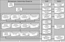
Fig.1. An apparatus for cutting and welding, operating on electrolysis products of a weak alkaline solution:
a - block diagram, b - ready-made homemade design:
1 - power supply with rectified mains voltage, 2 - electrolyser, 3 - liquid seal, 4 - gas burner, 5 - ammeter, 6 - knob for turning on the device, 7 - knob for changing the operating mode (abrupt change in power supplied to the load), 8 - knob controls potentiometers, 9 - bracket for storing the electrical cord in a folded state, 10 - portable wooden case, 11 - plug.
The productivity of the electrolyzer depends on the concentration of alkali in the solution and other factors. And most importantly - on the size and number of electrode plates, the distance between them, which, in turn, is determined by the parameters of the power supply - power and voltage (at the rate of 2...3 V per galvanic gap between two plates located next to each other ).
The designs of the direct current source I propose are available for manufacturing in a “home workshop” and for the novice DIYer. They are capable of ensuring reliable operation of even an “eighty-cell” (this one has 81 electrode plates) electrolyzer, and even more so a “thirty-cell” one. Option, fundamental electrical diagram which is shown in Fig. 4, also allows you to easily adjust the power for optimal matching with the load: in the first stage - 0...1.7 kW, in the second (when SA1 is turned on) - 1.7...3.4 kW.
And the corresponding plates for the electrolyzer are offered - 150x150 mm. They are made from roofing iron thick
0.5 mm. In addition to the 12-mm gas outlet hole, four more mounting holes (2.5 mm in diameter) are drilled in each plate, into which knitting or bicycle needles are threaded during assembly. The latter are needed for better centering of the plates and gaskets, and therefore are removed from the structure at the final stage of assembly.

Fig.2. Electrolyzer (“eighty-cell” version):
1 - side board (plywood, s12, 2 pcs.), 2 - transparent cheek (plexiglass, s4, 2 pcs.), 3 - electrode plate (tin, s0.5; 81 pcs.), 4 - sealing separating ring (5-mm acid- and alkali-resistant rubber, 82 pcs.), 5 - insulator sleeve (cambric tube 6.2x1, L35, 12 pcs.), 6 - MB stud (4 pcs.), 7 - MB nut with lock washer (8 pcs.), 8 - tube for flammable gas mixture outlet, 9 - slightly alkaline solution (2/3 of the internal volume of the electrolyzer), 10 - contact terminal (refined copper, 2 pcs.), 11 - fitting ("stainless steel"), 12 - union nut M10, 13 - fitting washer ("stainless steel"), 14 - cuff (acid- and alkali-resistant rubber), 15 - filler neck ("stainless steel"), 16 - union nut M18, 17 - filler neck washer (" stainless steel"), 18 - sealing washer (acid- and alkali-resistant rubber), 19 - filler cap ("stainless steel"), 20 - sealing gasket (acid- and alkali-resistant rubber).
Actually, I had to rack my brains a lot before the “water burner” became convenient and reliable, like an Edison lamp: turn it on and it started working, turn it off and it stopped working. A particularly troublesome task was the modernization not of the electrolyzer itself, but of the liquid seal connected to it at the output. But as soon as we abandoned the standard use of water as a barrier against the spread of flame inside the gas-forming battery (through the connecting tube) and turned to the use of... kerosene, everything immediately went smoothly.
Why was kerosene chosen? Firstly, because, unlike water, this liquid does not foam in the presence of alkali. Secondly, as practice has shown, if drops of kerosene accidentally fall into the burner flame, the flame does not go out - only a small flash is observed. Finally, thirdly: being a convenient “separator”, kerosene, when in the seal, turns out to be safe in terms of fire.
At the end of work, during a break, etc. the burner naturally goes out. A vacuum is formed in the electrolyzer, and kerosene flows from the right tank to the left (Fig. 3). Then - air barbation, after which the burner can be stored as long as you like: it is ready for use at any time. When it is turned on, the gas presses on the kerosene, which again flows into the right tank. Then gas bubbles begin...

Fig.3. Kerosene shutter and its principle of operation
(a - when the electrolyzer is running, b - when the device is turned off):
1 - cylinder (2 pcs.), 2 - plug (2 pcs.), 3 inlet fitting, 4 - outlet fitting, 5 - kerosene, 6 - adapter (steel pipe).
The connecting tubes in the device are polyvinyl chloride. Only a thin rubber hose leads to the burner itself. So after turning off the power, it is enough to bend this “rubber” with your hands - and the flame, finally giving out a light pop, will go out.
And one more subtlety. Although the power supply (see Fig. 4) is capable of providing electricity to a 3.4-kilowatt load, using such high power in amateur practice is very rare. And in order to “not drive the electronics” almost idle (in half-wave rectification mode, when the output is 0...1.7 kW), it is useful to have at your disposal another power source for the electrolyzer - smaller and simpler (Fig. 5).

Fig.4. Schematic diagram of the power supply unit.
In essence, this is a two-half-wave adjustable rectifier, known to many DIYers. Moreover, with “engines” of 470-ohm potentiometers connected to each other (mechanically). Structurally, such a connection can be achieved either using a simple gear transmission with two textolite gears, or using a more complex device such as a vernier (in a household radio).

Fig.5. A power supply option using thyristors and a homemade transformer in the circuit.
The transformer in the power supply is homemade. A set Ш16x32 made of transformer steel was used as a magnetic wire. The windings contain: primary - 2000 turns PEL-0.1; secondary - 2x220 turns PEL-0.3.
Practice shows: considered homemade apparatus for gas cutting and welding, even with the most intense use, it can serve properly for a very long time. However, thorough maintenance is required every 10 years, mainly due to the electrolyser. The plates of the latter, working in an aggressive environment, are covered with iron oxide, which begins to act as an insulator. The plates have to be washed and then sanded using an emery wheel. Moreover, replace four of them (at the negative pole), corroded by acidic residues that accumulate near the “minus”.
The use of so-called drain holes(except for the filler and gas outlet) can also hardly be considered justified, which was taken into account when developing the device. It is equally optional to introduce cans into the apparatus circuit to collect the accumulating super-aggressive alkali. In addition, the operation of the “tankless” design shows that no more than half a glass of this “harmful liquid” can accumulate at the bottom of a kerosene seal over a 10-year period. The accumulated alkali is removed (for example, during maintenance), and the next portion of clean kerosene is poured into the shutter.
V. Radkov, Tatarstan
MK 03 1997
This is a device that is delightful in the simplicity of its idea, and can be assembled at home with a minimum of tools and skills used (of course, in the advanced version everything becomes more complicated due to bells and whistles). The idea is very simple: we take electrodes, put them in the electrolyte, apply current, and collect hydrogen-oxygen at the output. Probably, anyone reading this text in childhood or later in life made a mini-electrolysis installation of the “entertaining physical chemistry” class: two pencils in a jar of salt or soda, a battery, wires, test tubes, and cheerfully set fire to hydrogen in a test tube.
no images were found
So, this is the same thing, only two or three orders of magnitude more powerful. This crap produces a powerful, extremely hot flame simply from water and alkali. No gas cylinders, no gearboxes, gas stations and other dregs - just apply voltage. And if you inflate her a balloon and release it with a burning thread...
What is needed to obtain a more or less powerful gas flow? That's right, a large area of electrodes, and the volume of gas per second is directly proportional to it. I won’t go into calculations, especially since I haven’t done them myself, I’ll just tell you the optimal parameters. The total area of the electrodes for a noteworthy gas flow must be at least 1000 cm^2 (total of the anode and cathode), preferably from 2000 cm^2. The current density should be on the order of 0.08-0.15A/cm^2 (8-15A/dm^2): with a higher current, overheating of the electrolyte and boiling will occur - that is, foam, thousands of it; with less, we lose in gas evolution. The drop on one pair of electrodes for such a current is 2-3 volts, depending on the electrolyte concentration (I took 10%, this corresponds to approximately 2.2-2.3 volt drop). Under such circumstances, pumping two huge plates with hundreds of amperes of current at two volts does not seem to be a very reasonable solution. It is much better to connect several cells in series: then we can increase the operating voltage and electrode area many times over at the same current. And now all that remains is to figure out that one electrode plate can be the cathode of one cell on one side, and the anode of another on the other.
In short, we simply assemble a Big Mac from plates alternating with ring-shaped gaskets. More plates means more voltage at the same current; the larger the area of each plate - more current at the same voltage. Increasing the number of plates increases the total voltage drop across them. The diagram shows everything clearly.


Now about the practical nuances of construction. First and most important: the material of the electrode plates. Since they will have to work in an aggressive environment (strong alkali, electrolytic reactions, temperature 50-80 degrees), there is only one choice available - stainless steel. But even here it’s not so simple, there are a lot of brands, and not all of them are suitable. By experimental (and also partly theoretical and partly comparative-analytical - study of descriptions of industrial electrolysis gas welding installations) a common and suitable steel was determined: 12Х18Н10Т.

Letters - additive metals (chrome, nickel, titanium); numbers - designations of their quantity (0.12% carbon, 18% chromium, 10% nickel, a little - up to 1.5% - titanium). It doesn’t matter, it’s a fairly fashionable and common steel and it’s not very difficult to find it in sheets with dimensions like 1000*2000 mm (I leave the method of cutting the sheet into plates to the discretion of those who want to replicate the device). Its analogue - AISI 321 - should also theoretically be suitable. I don't know, I haven't tried it. Titanium-free 08Х18Н10, for example, rusts and oxidizes, although it would seem to be completely suitable.
In each plate, it is necessary to make holes at the bottom and top at distances slightly less than the diameter of the gasket from each other (but not less than 0.5-1 cm from the edge of the gasket) - for gas exchange and for distributing the electrolyte among the cells. About a 5 mm drill is enough.

Don't forget to solder the wires to the outer parts of the plates before assembly.
Alkali. NaOH or KOH is suitable, preferably pure, not technical. Start with a concentration of 10% by weight (in distilled water), then experiment. Higher concentration means higher current, but more foam.

Almost all of the rubber gaskets sold are already oil and alkali resistant. I used o-rings (o-rings) of about 130 mm in diameter. You need one less of them than plates.
Tension plates. You need something very weakly bendable and rigid. The ideal and classic construction is thick, two-centimeter plexiglass. In it you can make conclusions and threads for gas and additional. fuel tank. I didn't have plexiglass, I just soldered it copper tubes into the last stainless plate, and used 27 mm plywood for the ties.

If all the above components - steel, gaskets, ties - are there, you can assemble them together, check with a small pressurization - the gaskets should not bulge and there should be no etching of air at all at a pressure of at least 0.5-0.6 atm, fill in alkali - and move on to external body kit.
First of all, you should make a water seal. The hydrogen-oxygen mixture, HHO, is an incredibly evil thing. It detonates easily and burns very quickly, without requiring any oxidizing agents (that is, oxygen).


If during operation a flame somehow slips into the hoses and reaches the electrolyzer, in the best case scenario, hot alkali mixed with pieces of gaskets will be scattered throughout the work area. But this is quite easy to avoid by setting simple design, the essence of which is clear from the diagram. The flame does not have a chance to jump down the bubbles through a layer of water or other liquid, and thus the combustion will not penetrate into the device itself. The structure is a little less than entirely assembled from plumbing fixtures from a hardware store.


Next you should take care of the burner. As a nozzle, the best we could find were thick all-metal needles (such as “Record” and the like) from Soviet reusable syringes. But since the idea of using the syringe itself as part of the burner is not the best, I simply tore off the nose of the syringe and soldered it to the nozzle on a full-fledged propane-oxygen burner.
And then follows important point. In view of the malice already mentioned above HHO In terms of combustion in general and especially its combustion speed, all possible places in the burner should be tightly, tamping, clogged with tangled small-small copper wires.

I used several meters of MGTF (there lived about 0.07 or less), thoroughly mixed into a copper pulp, which clogged almost the entire “barrel” of the burner and most of its spout. This will almost certainly prevent the flame from leaking into the hoses even if it is turned off incorrectly (and most certainly, in the event of an accidental breakthrough, the water seal will protect it). I really don’t recommend neglecting the volume and quantity of this copper waste. And it should start from almost the burner nozzle itself.
I won’t go into detail about little things like hoses, connections, pressure gauge connections, they are made from what’s at hand. Vinyl and silicone medical pipes have proven themselves well; they are easy to find in the right size that fits standard plumbing copper pipes of diameter.

Nutrition. As for power supply, everything is simple, how many volts and 8-15 amperes are needed. For now, I am using LATR and an OSM-0.63 (600 watt) transformer that steps down to 110 volts, after which there is a 50-amp diode bridge (with a reserve), a filter electrolyte and an ammeter to monitor the current. The voltage currently consumed is 68 volts, the current is 8-10A, respectively, the power is about 500-600 watts. If you expand the device to about 140 plates, direct network connection without a transformer will become possible, which will bring the device into a state of incredible cool and that’s what we plan to do as soon as I get it rubber gaskets- another 110 pieces.

In short, if everything is done, you can turn it on. It’s very lazy to describe possible problems that may appear; after all, this site does not have a set of “do it yourself for dummies” instructions. In short, this is it. First, there may be foam. Foam means dirty electrolyte, dirt on the plates, or overflow/overheating. If there is dirt, wait 20-30 minutes on a low current until it disappears. If there is overflow/overheating, reduce the current or let it cool. If the electrolyte is dirty, we use another alkali and distilled or at least melt water. Next, it can spit out alkali along with the gas. The electrolyte level is too high, drain it or let it run until it goes down. The pressure does not hold when the burner is closed - it is poisoning somewhere. Need to check. If the device is leaking alkali between the plates, you need to find out exactly where, look, and replace the gasket or plate. Nothing should leak anywhere, neither gas nor liquid. The gas flow is too weak, the flame jumps into the burner or burns the needle-nozzle - reduce the diameter of the nozzle or increase the gas emission power. By the way, when warming up, the plates can sag and short-circuit with each other - this needs to be monitored and something should be placed between the corners.

I recommend checking for combustion not indoors (otherwise it will go crazy, excuse my French, and everything will be alkali). I dragged him outside, and when I was sure it was safe, I brought him back inside. If everything is done correctly, at the end of the needle either a pale yellow-pinkish or quite bright yellow (the latter means sodium that has sneaked into the vapor) flame will light up, several centimeters long, almost silent, very difficult to blow out. By experimenting with the power input, electrolyte concentration and needle-nozzle diameters, you can achieve quite interesting results. By the way, this flame burns under water. The glass of the light bulb burns through, while thicker glass heats it white-hot and boils. Thin iron boils, thicker iron heats red and white. Melts (but with difficulty) quartz glass. In the video you can see what and how it can do.