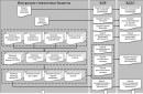
A muffle furnace is a heating device, inside of which there is a special casing - a muffle. It separates the inner working space from the firebox (heaters). Thus, the inner chamber protects the working area from carbon monoxide, and heated parts from interaction with these gases. How is the muffle constructed and is the muffle made?
The muffle protects the heating zone from gases or evaporation products of the heating elements. This creates conditions for heat treatment of parts, to saturate their surface with certain elements (carbon, nitrogen, chromium). The muffle is also used for melting gold and firing clay products.
In addition to its protective properties, the inner chamber ensures uniform temperature distribution throughout work area. This creates the same conditions for heat treatment of parts on the pallet.

Among the disadvantages of muffles, it is worth noting the low heating rate to high temperatures, which means the complexity of the high-speed heat treatment modes in such furnaces. In addition, heating the muffle itself requires additional expense energy, which means muffle furnaces are more expensive to operate than furnaces without a muffle.
Muffle furnaces: scope of application
Let us list the scope of application of muffle furnaces:
1. Metallurgical production and research in metallurgical laboratories. In muffle furnaces different sizes carry out heat treatment of parts made of various alloys - hardening and annealing, tempering and aging. Also in muffles, the surface is saturated with carbon, nitrogen, aluminum, silicon, and other elements (cementation, nitriding, cyanidation, diffuse metallization - chrome plating, aluminizing).

2. Remelting of gold and non-ferrous alloys, in which the saturation of the alloy with foreign impurities is unacceptable. In such remelting, it is necessary to limit the contact of the alloy with combustion products or with oxidation products of heating elements.
 Melting metal in a muffle furnace
 3. Firing of ceramics - used in the production of ceramic products (dishes, sculptural decorations made of clay). High-temperature firing ensures the strength of the ceramic surface and its water resistance.

4. Drying electrically conductive materials and elements.
 Drying materials in a muffle furnace
 5. Sterilization of instruments (in medicine).
 Sterilization of instruments in medicine
 6. Burning (cremation).

Features of a muffle furnace for melting metals
How muffle furnaces work: design
Main structural element furnaces - muffle. Parts for heat treatment (or gold for remelting, medical instrument for heat treatment, ceramics for firing). The muffle is made from a chemically inert material.
The muffle chamber is located inside the furnace. In this case, the space between the outer casing and the inner chamber is filled with a heat insulator. High-quality thermal insulation determines Operating efficiency device, as well as its safety (it limits the strong heating of the casing and prevents the possibility of getting burned on it).

The heating elements are located outside the muffle or in its walls. They heat the inner chamber, which in turn transfers heat to the workspace. The operation of the heating elements is controlled by the regulator. It controls the temperature and heating time, the entire heat treatment process. The level of automatic control affects the price of the heating device. The more regulatory functions, the more expensive the stove.
Muffle: design and materials
The following materials are used to make the inner chamber:
- ceramics;
- ceramic fiber;
- corundum;
- fireproof (fireclay) brick.
The choice of material for making the muffle is determined by the operating conditions and purpose of the furnace. For example, a muffle made of refractory fibers is used for heating in a neutral environment. Corundum chambers - can be used in chemical environments. But the ceramic muffle is universal. Due to its inertness, it is used for various tasks (melting, heat treatment, roasting).

The same housing can be loaded with muffles from different materials(for different heating and processing purposes). Thus, the inner chamber is a replaceable element, which can be in the form of a pot or a cap, loaded from the side or from the top. Structurally, muffles are divided into the following groups:
- Bell-type (they are loaded from above in the form of a bell, and after heating they are separated from the hearth).
- Potted (also loaded from above, but have the form of a container and are not separated from the hearth).
- Simple (the cage is loaded from the side of the furnace).
Heating elements
To heat the walls of the inner chamber, heating elements are installed. They use wire made of heat-resistant metal or alloy. When current passes through the wires, they heat up and generate heat. To increase the recoil area, the wire is wound in the form of a spiral.

There are also open and closed heaters. Open heaters have more high speed heating, if damaged, they can be easily replaced with new ones. But at the same time, they oxidize faster (due to heating) and fail more often.
Closed heaters are located inside the walls of the muffle. They are protected from oxidation, therefore more durable. Disadvantages: longer heating time and higher repair costs (in case of breakdown, the entire muffle must be replaced).
Types of muffle furnaces
Muffle furnaces are classified according to several criteria. They are divided according to the method of heating:
- electrical;

- gas.

By type of protective atmosphere:
- Air (the muffle limits the mixing of air between the workspace and the heaters).
- Vacuum (a rarefied space is created inside the muffle - a vacuum).
- Furnaces with a special atmosphere - the space inside the muffle is filled with a special gas (inert, nitriding, reducing, etc.).
The operating temperature inside the oven can vary from +400ºC to 2500ºC. Based on this criterion, muffle furnaces are classified into types:
- For moderate heating - up to 500ºC.
- For medium temperatures - up to 900ºC.
- For high temperatures - up to 1400ºC.
- For extremely high temperatures - up to 2000-2500ºC.
Note: The heating temperature determines the price of the stove. The hotter the oven heats, the higher its cost. In addition, the prices of muffles depend on the size and functional equipment (presence of thermocouples, type of heaters, automation).
You can assemble it yourself at home simple design ovens. In this case, the do-it-yourself muffle furnace will operate on electricity. The main element - the muffle - can be made of clay or folded from.
For a clay muffle, a blank is made from cardboard or plywood. The resulting box is covered with a layer of clay 1 cm thick, dried until hardened (3-5 days) and fired in a coal oven. The firing temperature is 700-800ºC. This is enough to vitrify the clay structure and create a strong inner chamber.
 DIY muffle furnace
 The resulting ceramic muffle is wrapped with wire (nichrome or fechral, 1 mm in diameter) - it will work as a heating element. In order to secure the wire to the casing, it is covered with a second layer of clay (which is also dried and fired in a coal oven). The ends of the wire for further connection to the electrical network are left open.
To fold the fireclay muffle, grooves are made in each brick (for the location of heating coils). After stacking the bricks, spiral wire is placed in the grooves. To secure it in the grooves, the spiral is coated with clay or reinforced with wire.
The finished inner chamber is placed in metal case. It is welded from steel sheets with a thickness of 2 mm or more. Holes are left in the body for connection to the heating wire.
The finished muffle is placed inside the casing, the contacts are connected and thermal insulation is made. Used as an insulating material basalt wool or asbestos chips (asbestos is a more harmful option; when it is heated, carcinogens are released).
Note: This do-it-yourself muffle furnace allows you to fire ceramic products. For metallurgical annealing or remelting of non-ferrous alloys, an industrial furnace is required.
Self-production of a muffle furnace
SNOL stoves: prices and models
The manufacturer of electric furnaces SNOL offers various heating furnaces and chambers. Muffle versions of SNOL are laboratory electric furnaces for heat treatment of parts in air. They are equipped with electric spiral heaters and a rectangular inner chamber. Scope of application of SNOL furnaces: thermal and chemical-thermal treatment, heating of samples, calcination.
The SNOL model range provides ovens with different operating temperatures and different working space volumes. The operating temperatures of SNOL are 100-1300ºC. In custom-made models, operating temperatures can be higher - up to 1600ºC. The volume of the working chambers is 3, 6 or 10 liters. Semi-closed and closed heaters are used. In versions with a working chamber volume of 3 and 6 l, the heaters are located with three sides. In versions with a 10 l chamber, there are heaters on 4 sides of the inner chamber.
 Muffle furnace SNOL
 The muffle material is ceramic or fiber. There are SNOL models in which the inner chamber is made of stainless steel and brick. Modular design The oven allows you to quickly and easily replace any element if necessary.
The quality and reliability of operation of SNOL heating devices is ensured by Japanese programmable thermostats and fechral heaters.
Prices for SNOL stoves are affordable.
A muffle furnace is a device necessary for the operation of a metallurgical laboratory. It is also in demand in jewelry and ceramic production, used in medicine (for instrument processing). The design is simple. For annealing ceramic products, you can make a muffle with your own hands. For more critical types of chemical-thermal treatment, it is better to purchase a factory-made oven. This will guarantee its quality and safety.
Description of the operation of the muffle furnace Snol-7.2/1100
A muffle furnace is a device for heating various parts and materials to the required temperature. They call it a muffle closed chamber to place the material. The muffle protects the material from the effects of fuel combustion products. It can be made from various materials– ceramics, MKRV, steel, brick.
What types of ovens are there?
There are several main parameters by which muffle furnaces differ:
- heating method;
- furnace design;
- temperature range;
- protective environment.
According to the heating method, they are distinguished:
- gas muffle furnace;
- electric muffle furnace.
The method of loading the material determines the design of the device. Furnaces produced:
- with vertical loading;
- with horizontal loading;
- bell-type (lifted from the floor);
- tubular (for heating thermocouples).
According to the heating range, there are heating furnaces:
- to moderate temperatures (from 100 to 500°C);
- to medium temperatures: (from 400 to 900°C);
- to high temperatures (from 900 to 1400°C);
- up to ultra-high temperatures (up to 2000°C).
Heating of the material in the muffle can occur in different environments:
- air;
- vacuum;
- various gases.
The heating element in furnaces can be open or closed. The number of heating elements depends on the dimensions of the device.
The advantages of open elements are a high heating rate and no problems with replacement in case of failure. But they are more corrosive and are affected by harmful substances produced when heated.
Closed ones are built into the muffle. They heat up more slowly. If it breaks, the entire chamber must be replaced. But they are not affected by harmful substances and last longer.
How is the temperature adjusted?
To regulate the temperature, special thermostats are installed for the muffle furnace. They can be of two types:
- analog;
- digital.
Analog ones have hardly been used lately due to high errors. They consist of a rotary switch with marked marks and a temperature scale. Turn the knob to set the required heating temperature.
Currently, digital thermostats are more often used. They can be:
- with one display showing the set or actual temperature;
- with two displays that show both the set and actual temperature;
- with programmer for selecting different operating modes.
Purchasing ovens with a programmer is necessary when long process heating with changing temperature conditions without human intervention. But most often there is no such need. Therefore, ovens with programmers are used much less frequently.
Applications and furnace selection
The scope of application of muffle furnaces is quite diverse. They are used for firing ceramic products, foundry molds, in the manufacture of jewelry and wax products, and for melting non-ferrous metals.
When choosing a furnace, it is necessary to take into account many factors - the size of the workpieces to be heated, temperature conditions, purpose of application.
For training, a furnace with a small muffle size (100x100x100) and a high heating temperature is suitable. Such furnaces are called “mini-muffle furnaces”.
Jewelry workshops need a professional oven with a programmer. To heat precious metals, accuracy of adjustment is very important and several operating modes are needed. In jewelry making, enamel muffle furnaces are used to apply enamel to precious metals.

In dentistry, when making dentures, a furnace with small dimensions and high temperature is needed.
In industry, furnaces with large dimensions (at least 200x200x200) and ultra-high temperatures are used - up to 2000 degrees. Accordingly, the price of such a device is much higher.
The laboratory muffle furnace is used for carrying out laboratory analyses, heating samples and materials, and conducting tests. Dimensions and temperatures depend on the tests performed. For such furnaces, a wide range of parameter adjustments is important.
The SNOL muffle furnace is a laboratory resistance furnace, chamber-type with a rectangular muffle for heating in an air environment with normal pressure.
Electric chamber furnaces of the SNOL type for testing were called “EKPS muffle furnaces”.

Electric furnaces are available with chambers made of ceramics or heat-resistant fibrous material. Ceramics are much more reliable and durable than fiber, do not require large energy consumption, and allow maintaining temperature uniformity. But ceramics take a long time to cool down and heat up. Therefore, it is not possible to quickly change the processing mode.
Fibrous ones also have their advantages. In them, the heating elements are pressed into the fiber and their radiation does not affect the heated material. But they have many more disadvantages: high energy consumption, emission of harmful gases, fragility. For withdrawal harmful substances Ventilation is provided in the ovens.
Additional equipment
To make it easier to work with the oven, a number of additional components are provided:
- SiC – plate (to protect the muffle);
- heat-resistant gloves;
- forceps;
- if you have a programmer, you must purchase software;
- set of spare parts (heaters).
These components must be purchased separately.
For most people, muffle furnaces are completely useless. At the same time, furnaces are necessary for those whose profession or hobby involves making jewelry, firing ceramics, or smelting metals. Moreover, muffle furnaces are used in the creation of single crystals, cupellation, and also in medicine for high-temperature sterilization.
The cheapest factory models cost about 30,000 rubles, which significantly hits the pockets of home craftsmen. But if you remember school courses physics, in particular thermodynamics, then it is quite possible to build such a structure with your own hands.

Depending on the design features of the furnace, there can be:
- tubular;
- cylindrical shape;
- vertical arrangement;
- horizontal arrangement (the simplest option).
Heat treatment can be carried out in air, vacuum or inert gas, but at home only the first option is possible.
Depending on the type of heating element, muffle devices are:
- gas;
- electric.
Operating gas appliances is cheaper, but making them yourself is prohibited by law. Electric ones are more expensive, but have a significant advantage - the ability to accurately regulate the temperature.
Important! A homemade muffle furnace can be given any shape and dimensions, made in a style that would suit general interior Houses.

What will be required at work
The most convenient to use is vertical design. To make it you will need:
- grinder, metal circles;
- wire cutters;
- welding machine;
- nichrome wire, ø1 mm;
- steel sheet 2.5 mm thick;
- basalt wool;
- corners;
- fireclay brick;
- silicone sealant;
- fire-resistant mixture;
- respirator, plastic glasses.
Main design elements

Important! A muffle furnace consumes quite a lot of electricity. For example, a device capable of heating up to 1000ᵒC requires about 4 kW. The electrical wiring with which the stove will be connected to the network must withstand heavy loads. You will also need a machine with a 25 A stabilizer.

Important! Asbestos should not be used for this, since when heated it can release carcinogens.
Case manufacturing
A rectangle of appropriate dimensions is cut out of a steel sheet, bent to a radius, and the seam is welded using welding machine. The resulting cylinder is coated with fire-resistant paint and as soon as it dries, the bottom (a circle cut from the same sheet) is welded to it. The bottom and walls are additionally reinforced with reinforcement. The volume of the cylinder must be calculated in such a way that thermal insulation can be placed in it.

Important! When using, for example, an oven, the bottom also needs to be reinforced with corners.
Do-it-yourself muffle furnace: manufacturing instructions
Stage one. The inside of the cylinder is lined with basalt wool.


Stage two.

Thermal insulation is being constructed, for which, as mentioned earlier, you only need to take fireclay bricks. The procedure is as follows: seven bricks must be joined in the body so that they form a pipe. In the future it will serve as a working chamber.

The bricks are laid out in a row, and marks are made on each of them at which they will be cut. Next comes the actual cutting, after which the bricks must be of such a shape that they can be connected into one hollow pipe. To simplify the procedure, the bricks can be numbered. At the end of cutting, the pipe is assembled, tied with wire, and the symmetry of the shape is checked. If necessary, adjustments are made. Important! Cutting must be done on fresh air
, preferably in a ventilated place, not forgetting about personal protective equipment (respirator, overalls, goggles).

Stage three. Nichrome wire is twisted into a ø6 mm spiral by winding it onto a base (used electrode, pencil, etc.). The brick is then removed from the body and placed back in a row.. As a result, the laid spiral should lead from the bottom to the top of the pipe. Contact of the turns is not allowed, as this may cause a short circuit.
Stage five. To bring out the ends of the spiral and connect them to the machine with a stabilizer, three strips cut from ceramic tiles , with polypropylene and wire channels made. These channels will greatly simplify renovation work
in future.

Stage six.
The finished structure is placed in a steel case. In this case, one brick is placed on the bottom of the body, pre-coated with fire-resistant glue. To remove the ceramic channels, holes are made in the housing in appropriate places.


Important! The spiral can only be turned on after the structure has dried, otherwise the wire will be damaged.
Test run. To allow the structure to dry completely, place it in a warm, well-ventilated place. The use of any heating devices is prohibited as this may lead to cracking of the masonry. After drying, the coils are connected to a machine with a stabilizer, and the heating power and operating temperature are adjusted.
Important! To check the dryness of the masonry, you need to turn on the device at full power and see if it evaporates.
work surface
steam. When operating the oven, the lid must be tightly closed. Muffle furnace for ceramics
Even in daylight, you will notice that soon after turning on the sides of the pot will glow dark red. From this moment the firing countdown begins, from five to twelve hours, depending on what is being fired. If overheating is observed, the power is slightly reduced.
Stove made of earthenware barrel
You can also make a larger stove from a faience barrel.
Stage one.
First, a small hole is made at the bottom of the barrel with a diamond drill to release the expanded air.
Stage two.
Next you need to do under. To do this, a “foundation” of fireclay bricks is assembled on a small sheet of steel and connected with metal corners. Then, in the upper part of the barrel, grooves are made for the spiral (no more than three or four) - the heating element of the required power will be placed in them.
Stage three.
- All that remains is to make the outer shell of galvanized steel. It is made removable, since it will be put on only after covering the product with a muffle (barrel). The space between the muffle and the outer shell is filled with asbestos.
- The firing procedure is no different from the previous version, but the temperature is adjusted using a thermocouple. The walls of the barrel are thick; by the time they light up (even without the outer shell), the ceramic product will already be burnt.
- Safety precautions
- Only persons who are familiar with the safety precautions for operating electrical appliances should operate the muffle furnace.
- You cannot start work without personal protective equipment - gloves, goggles, special clothing.
- The structure can only be switched on with grounding.
Do not start work if there are chips, cracks or other structural defects.
The oven must always be supervised.
After switching on, do not touch the heating element (coil).
Despite numerous advantages, muffle furnaces, especially small ones, are still not very common among home craftsmen. For a more detailed look at the design, watch the video below.
Video - Muffle furnace


Master Kudelya © 2013 Copying of site materials is permitted only with indication of the author and a direct link to the source site. The oven power is 500 W, the theoretical temperature is up to 800 degrees, but I didn’t heat it up to there, because I have a more serious oven for that. The peculiarity of this design is its extreme simplicity and extremely low cost of components. Such a design can be made from scrap materials in just a few days, of which most of the time will be spent on drying the furnace muffle.
The upper body of the oven with the door open.
The muffle itself is located in the center of the body. The door is thermally insulated, as can be seen in the photo, using asbestos cardboard on studs. The window is covered with two layers of mica with some gap between the layers.
Muffle furnace assembly. It consists of two bodies fastened together. The muffle itself is located in the upper housing, and the control unit is located in the lower housing.
I immediately advise you to make a stove like mine in different buildings. This will allow you not to worry about cooling the control unit with various fans. The upper housing will heat up and create a draft, which, combined with the perforations in the lower housing, will be sufficient to cool the temperature controller.
Making a muffle. The muffle can be made in many ways different ways


. You can take a ready-made ceramic pipe. It's best to use mullite-silica MKR, or a pipe from an old rheostat or a large fuse. If you prefer a rectangular chamber, it is better to sculpt it yourself. Since my site is focused on those practical designs that I managed to make myself, here is the recipe for my muffle.
Kaolin (kaolin clay) - 1 part. Can be found near the porcelain factory. They are brought by wagons for the production of porcelain, earthenware, and electrical ceramics. If not, any thicker clay will do.
Sand - 3 parts. Quarry sand is better than river sand.
Mix all this thoroughly, mix with water until the lump has not yet spread, but holds its shape, and leave in a plastic bag for a couple of days. Then take it out and mix again until smooth. Then we sculpt the muffle.
Retreat.


So, modeling the muffle. The rectangular muffle is molded in a rectangular plywood or krags box. A muffle with a level bottom and an arched vault is molded in the same box. The size of the box is equal to the outer size of the muffle plus 3-6% shrinkage. It is always molded from the inside of the box, since the muffle shrinks during drying and when molding from the outside, cracks are inevitable. To prevent the mixture from sticking to the walls of the box, the inside walls are lined with polyethylene. If the mixture is semi-dry, then you can put paper. This way you can save drying time.
After the muffle is fashioned, it is left to dry for several days. When the walls of the muffle gain the necessary strength, turn the box over and remove it from the muffle. Further, if the muffle is not strong enough for spiral winding, it is dried for several days on a radiator or in an oven. Then it is slowly fired to 900 degrees. If you have problems with firing, as a last resort you can leave a dry, unfired muffle. But the strength will no longer be the same.
If the muffle is strong enough, then it is wrapped in a spiral, a coating is applied, and the entire assembly is dried and fired. It is preferable to do this when assembled, since the coating will stick better to the half-baked muffle. Make sure that there are no voids inside the spiral, everything is filled with coating. Otherwise there will be local overheating of the nichrome.
Heater calculation.
There are a lot of materials on the Internet about heater calculations. All of them have varying degrees of scientific knowledge of this issue. For example, you can not only read various considerations, but also calculate the heater using the built-in calculator. The input data is the furnace power, heater material, temperatures of the heater and the heated product, design and placement of the heaters. At the output we get the diameter and length of the heater wire. But upon closer examination, it turns out that the diameter was chosen for reasons of saving wire material and the operating conditions are close to ideal. In life, the opposite is usually true. Usually there is a skein of old nichrome in the bins and its owner is tormented by the question of whether it can be used for the benefit of a person. And there are also continuous questions with the power of the furnace.
Therefore, I will give my calculation method, although not so scientific, but based on my experience in manufacturing such devices.
So, the first thing you need to decide is the power of the furnace. The power directly depends on the size of the muffle and the lining used. You determine the size (volume) of the muffle yourself, depending on the size of the heated products.
For modern stoves using fiber heat insulators (MKRV, ShPV-350, etc.), the approximate power per liter of volume will be:
Furnace chamber volume (liters) Specific power (W/liter)
1-5
500-300
5-10
300-120
10-50
120-80
50-100
80-60
100-500
60-50
Let's say, for example, your chamber volume is 3 liters, so the oven power will be 1200 W. My muffle volume is a little more than a liter, so let’s take the heater power to 500 W.
Next, we calculate the current through the heater :
I = P/U= 500/220 = 2.27 A
And the heater resistance value
R = U/I = 220/2.27 = 97 Ohm
Next, we climb into the bins and look at the diameter of the existing nichrome. I found nichrome with a diameter of 0.65 mm. Next, using the table, we estimate whether our nichrome can withstand such a current.
Diameter (mm) 0.17 0.3 0.45 0.55 0.65 0.75 0.85
Allowable current (A) 1 2 3 4 5 6 7
As you can see, with a diameter of 0.65, the permissible current is 5 A, so it will withstand our 2.27 A with a large margin. In general, when making a heater, you need to take thicker wire, because the thicker the wire, the longer the temperature it can withstand and the service life.
Maximum operating temperatures of heating elements. Here:
GS 40 Nichrome
GS 23-5 Eurofechral
GS SY Superfehral
GS T Eurofehral

BUT! This is a double-edged sword. We cannot greatly thicken the diameter of the wire, because in order to obtain a calculated resistance of 97 Ohms, we will have to greatly increase the length of the wire, which may not be acceptable for design reasons.
Using the table, we determine the nominal resistance of 1 linear meter of wire. Here:
GS 40 Nichrome
GS 23-5 Eurofechral
GS SY Superfehral
GS T Eurofehral

So, from the table for a diameter of 0.65 mm we take (and confirm by subsequent measurement with the device), the nominal resistance is 3.2 ohm/meter. Therefore, the length of the wire will be:
L = R/3.2 = 97/3.2 = 30 Meters
This is the price to pay for the excess wire diameter in excess footage. But this is not a problem, because I will not wind this wire as it is, and there is a danger of not keeping track and allowing an interturn short circuit on our muffle. This wire needs to be wound onto the rod. The tip of the wire together with the rod is clamped into the chuck of a drilling machine, or at worst, the chuck of a hand drill. The wire is fed under slight tension.

When winding, the following recommendations must be observed. The diameter of the rod for winding wire with a diameter of up to 4.5 mm must be no less than:
- for nichrome, four times the diameter of the wire;
- for fechrals, five times the diameter of the wire.
For all alloys with a diameter greater than 4.5 mm, at least six times the diameter of the wire.
There is another ambush when working with fechral. Fechral, unlike nichrome, becomes brittle after calcination, so it is no longer worth beating.
Finished spiral stretch evenly to a length comfortable for winding the muffle. But no more, because it will be much more difficult to compress evenly. We wrap the muffle along the grooves and apply coating, as in Fig. 4.
Next, we place our muffle in a metal case.


The main lining is made of blocks of lightweight fireclay bricks ШЛ-0.4. Brick is easily processed with the tool previously described. Note the hole in the back block of the lightweight for the thermocouple and two holes for the nichrome leads.
During installation, the side wall of the muffle was damaged, but this is not a big deal, it will be restored with the same compound after installation.

I would like to warn you against some ambushes that may await you when making the lining.
First of all, I want to warn you if you are tempted to use asbestos. Yes, it melts at 1500 degrees, but at 800 degrees it loses chemically bound water and turns into powder. Therefore, products made from it, such as cardboard or cord, can work up to this temperature. In addition, fechral should not come into contact with asbestos. I used it because this stove is sharpened to this temperature and I have nichrome.
Further, regarding the use as a binder liquid glass. It can be used for sculpting muffles operating up to 1088 degrees; when this temperature is exceeded, the muffle will float. In addition, fechral also does not like contact with liquid glass.
Regarding the use of fibrous materials on a mineral (basalt) basis, I will repeat what I wrote on one of the forums. It's almost the same thing. Produced by melt blowing. Holds temperature well. But they have a binder that will not withstand even 250 degrees. But on the Internet, cunning sellers cite the fire resistance of the fiber itself. Formally, they are right. But they don’t write that after the first calcination the binder will burn out and they will fall off in a heap. There are varieties with a refractory binder, but there is very little information. Only indirect signs - for example, intended for baths and fireplaces. And again the fire resistance of the fiber itself is tested. And needless to say, the fechral doesn’t like them either. So if you have the opportunity to fly, it is better to use already proven ones. And of the ones I tested, mullite-silica felts, for example, MKRVKh-250 (1300 g), are most suitable.
By the way, in Sukhoi Log they have launched the production of ceramic blankets Cerablanket, Cerachem Blanket, Cerachrom Blanket. I dealt with the first of them; it can withstand the direct flame of a burner. The last two are even more fireproof. But I haven't tried them myself.
There are descriptions of furnaces floating around the Internet, which are all being torn apart from each other, in which fireclay clay appears as a muffle material. Ordinary clay has a high shrinkage and is used as a binder. Chamotte is nothing more than baked clay. Fireclay is not molded, it is used as a filler and requires a binder, for example, ordinary unfired clay. Therefore, what is meant by the expression fireclay clay is completely unclear.
Control block.
Since I promised a description of the most budgetary, the simplest oven, then the temperature controller will be appropriate. A good inexpensive regulator Sh-4501, which can be purchased at a price of 1 to 2 thousand rubles. The cheapest and most cheerful regulator. Available with temperature measurement and control ranges from 0-200 to 0-1600 degrees. As a measuring element, thermocouples XK, XA and PP.
Technical description and operating instructions for the Sh4501 regulating millivoltmeter. Read at your leisure.
Front panel of the control unit. This version of the regulator is for the range from 0 to 800 degrees, thermocouple XA.
Below from right to left is the control unit switch, neon lamp TLO (orange) to indicate the voltage supply to the load, TLZ lamp (green) to indicate load disconnection and a red lamp to indicate thermocouple breakage.


Connections on the back side of Ш4501. For those who don’t understand, the plastic cover once again shows the wiring diagram. Please pay attention - the compensation wire must go all the way to the terminal block with the compensation coil.
Such fittings for indicator lamps are no longer produced, so I recommend using modern types XB2-EV161. They come in red, yellow, green, white and blue. Electrical diagram of the control unit. If you do not find a sufficiently powerful toggle switch for turning on the control unit, then place it after the contacts of the PE23 relay. The relay comes complete with the Sh4501 device. The power of the relay contacts is 500 VA in the alternating current circuit.

Implementation of installation of the control unit in this box. The regulator is tucked into the front of the skis. The connector is connected (on the right). The relay is mounted on the back cover from the inside.


Furnace assembly. Back view. As you can see, the thermocouple wires and heater leads are simply cooled in air, without any frills. The heater wires are connected through a terminal block, preferably with a ceramic base. I recommend using a ceramic socket from a socket or a ceramic lamp socket.
The thermocouple leads are also through the terminal block. A piece of compensation wire corresponding to the graduation is connected to the same terminal block contacts. If this is an ordinary wire, then the device will lie on the value of the temperature difference between this terminal block and the rear panel of the Sh4501 with the measuring coil. An overhead socket for connecting the load is mounted on the outside of the back cover, and a terminal block for connecting a thermocouple is mounted on the back cover of the muffle box. This allows you to use this control unit not only with this muffle, but also for temperature control in your other devices. It is enough to screw a thermocouple of this calibration to the terminal block and insert the plug into the socket.
A little about a homemade thermocouple. For the final budget of our furnace, I used a homemade thermocouple with XA calibration. I prefer homemade thermocouples not out of greed, but simply because they have less inertia compared to factory ones. Although there is a risk of burning the regulator input circuits. I will not dwell in detail on the manufacture of such a thermocouple, because this process is well covered in the literature (Bastanov. 300 practical advice) and on the Internet.

The material was cores from compensation wire of HA calibration. The ends are welded with a tungsten electrode in an argon atmosphere. If you weld it this way, it’s weak, whereas it’s described in books in graphite with borax using a powerful transformer. Then the thermocouple is inserted into a ceramic two-channel MCR tube. At this point, sorry, you'll have to fork out the cash.
Heating chamber assembly. The wall has been finished, the cracks have been sealed. Then some excess putty is applied around the mouth of the muffle. Then it is covered with polyethylene and the lid is closed.
Muffle assembled. After laying the spiral, it is coated with the same composition that the muffle is made of. The ends of the spiral are secured with a loop made of glass tape with mica. Don't forget to put a mounting rod under the spiral. When the muffle dries, the rod is removed and a hole remains for the thermocouple.
Muffle without strapping. Pay attention to the grooves on the corners of the muffle. They are designed to ensure that the spiral does not move during coating. At the bottom there is a groove for a thermocouple. The thermocouple should be in close proximity to the coil.
Based on the type of fuel used, the muffle furnace can be of two types:
- gas;
- electric.
Important! It is not possible to make a gas stove yourself, since this is prohibited by current legislation.
Regarding the design, the following types of furnaces are distinguished:
- Horizontal, which are the simplest;
- Potted type or vertical;
- Tubular;
- Bell bells.
Heating of such furnaces can be carried out in a vacuum, air or gas environment. The muffle furnace that you will build with your own hands may only provide an air environment for processing products.
Important! In addition to saving money, making such a stove yourself is advantageous in that the master can create a design of the most convenient volume and shape for himself.
What does a muffle furnace consist of?
The operation diagram of a muffle furnace becomes clear when considering the main details of this design.

Let's look at what parts a muffle furnace includes:
- Furnace body. IN in this case It will be most convenient to use an old gas stove equipped with an oven, which will be used as the basis for the structure.
Advice! If used as a housing gas stove, then you must first dismantle all plastic parts. With absence finished design the body is welded from sheet metal, more than two millimeters thick.
- Inner layer, which is in direct contact with the surface of the firebox. It is very important, since the efficiency of the furnace structure depends on it. Fire-resistant fireclay bricks should be used as the inner layer.
- Outer layer. It is designed to reduce heat loss from the oven. You can use basalt wool or perlite.
Advice! It is undesirable to use asbestos as an external furnace layer, since when heated, this material releases carcinogenic substances into the atmosphere.
- Elements involved in direct heating of the workspace. In muffle furnaces, such elements most often are spirals, which are twisted from fechral or nichrome wire, about 1 mm thick. By the way, nichrome wire is a more desirable option due to its corrosion resistance and high ductility. At the same time, fechral wire has a lower cost.

Drawing of a furnace with a rectangular muffle: 1 - regulating millivoltmeter; 2 — signal lamp; 3-fuse; 4 - switch; 5-control unit; 6- heating chamber; 7-body; 8-ceramic muffle; 9-heat. element; 10-thermal insulation; 11 — counterweight; 12-door; 13 — hole for control thermocouple; 14-hole for regulating thermometer.
You can take examples of dimensions, power and volume based on SNOL brand furnaces in the table below.
| Furnace model | Volume, l | Temperature, °C | power, kWt | Number of phases | Width x Length x Height, mm. | Weight, kg | |
| Working chamber | Dimensions | ||||||
| SNOL 3/10 | 3 | 1050 | 1,8 | 1 | 150×200×100 | 425×530×520 | 30 |
| SNOL 3/11 | 1150 | ||||||
| SKV (SNOL) 6/10 | 6 | 1050 | 2,2 | 180×270×130 | 450×600×545 | 40 | |
| SKV (SNOL) 6/11 | 1150 | ||||||
| SNOL 10/10 | 10 | 1050 | 4 | 200×300×180 | 470×620×595 | 50 | |
| SKV (SNOL) 10/11 | 1150 | ||||||
| SNOL 3/10-V | 3 | 1050 | 1,8 | 1 | 150×200×100 | 425×610×650 | 32 |
| SNOL 3/11-B | 1150 | ||||||
| SKV (SNOL) 6/10-V | 6 | 1050 | 2,2 | 180×270×130 | 450×680×675 | 42 | |
| SNOL 6/11-B | 1150 | ||||||
| SKV (SNOL) 10/10-V | 10 | 1050 | 4 | 200×300×180 | 470×700×725 | 52 | |
| SNOL 10/11-B | 1150 | ||||||
Abbreviation of the form SNOL used to designate the type electric ovens. C - resistance, refers to the type of heating elements (resistive type). N - chamber type, with a rectangular section of the furnace chamber. O - for processing parts/materials in air at normal pressure. L - laboratory, i.e. allowing temperature adjustment over a wide range.
How to make your own muffle furnace

A muffle furnace for ceramics has a similar manufacturing procedure, regardless of the horizontal or vertical layout. The only difference is the arrangement of the elements. Let us consider the process of manufacturing a muffle furnace for firing ceramics in more detail:
- As mentioned above, the best option for the body is ready gas oven or a structure made from sheet metal. To do this, using a grinder, you need to cut a rectangular strip of the size suggested by the drawing. Next, it is bent into a radius, after which the seam is hermetically sealed. Thus, a cylinder is obtained.
Video about making muffle furnaces yourself from a professional craftsman
Advice! To prevent corrosion, the metal can be exposed with several layers of fire-resistant paint.
- We weld the bottom to the resulting structure, for which you need to cut a circle of the required diameter from a sheet of steel.
- To strengthen the bottom and walls of the housing, it is necessary to use reinforcement. The housing must be of such a size that it can easily accommodate thermal insulation and a fireclay brick structure.

Important! Can also be used as a structure body old refrigerator. In this case, it also needs to be strengthened with metal tubes and corners.
- The inside of the body is lined with a thick layer of basalt wool.
- Now we make a heat accumulator. To do this, you need to join 6-7 bricks, as in the photo below. This will be the working chamber of the future design. To make it, you need to cut the bricks at an angle so that they can be used to assemble a structure in the form of a pipe. Trimming should be done using a grinder.

Advice! For ease of use, the bricks can be numbered. After cutting, we assemble the structure. When cutting bricks, it is very important to ensure reliable protection for the eyes and respiratory tract. Work must be carried out indoors with good ventilation, or even better - outdoors.
- We make a spiral from a coil of wire, the diameter of which should be about 6 mm. For these purposes, nichrome or fechral wire is excellent, which can be wound on a thin metal rod or pencil.
- The bricks used to make the working chamber are laid out on flat surface. It is necessary to make special grooves in them to accommodate the spiral. A grinder is used for this.

Important! The wire should be laid in a spiral in a brick structure. It is very important that the turns do not touch each other. Otherwise, a short circuit may occur.
- To extend the ends of the wire outside the chamber, it is necessary to prepare three long and thin pieces of ceramic tiles. Thin channels for the wire are first sawed into them, after which these sections are inserted between adjacent bricks. Such ceramic terminals can significantly facilitate the operation of equipment in the future, allowing repair work to be carried out simply and quickly.

Three pieces of tile allow you to use the oven at three power levels. To do this, you will need to include different spiral contours:
- To turn on the first power stage, it is necessary to turn on two spiral circuits in series.
- To operate the device in the second mode, you need to separately connect the lower spiral.
- The third stage involves parallel connection of two circuits.
Advice! The inclusion of spirals must necessarily provide for grounding!
- Now that the design of the working chamber is completely ready, it must be wrapped in a layer of thermal insulation and placed in the furnace body. The camera is installed on a brick, which will act as its bottom. It is pre-coated with fireproof glue or clay.
- To remove the ceramic channels outside the body, it is necessary to drill holes in it in the appropriate places.

- Sheet steel is also used to make the lid. It is necessary to cut a circle to the size of the oven. A latch, canopies and handles are welded onto the lid. To seal the structure, it is necessary to apply a layer of silicone along the edges of the lid and on the adjacent walls of the structure. To do this, the surfaces are pre-degreased.
After the structure is completely dry, you can connect the wire to electricity through a stabilizer. At this stage, the furnace undergoes testing, during which the power of the muffle furnace is adjusted to obtain the required operating temperature at each stage.

Advice! To make sure that the furnace structure is completely dry, it is turned on at maximum power and checked for the presence of fumes. If there is no steam coming from the surface of the oven, this means that it is completely dry.
Conclusion
An analogue of the PM 8 stove can be easily made at home. Wherein homemade design has excellent technical characteristics and is able to compete with factory-made analogues.